Of crucial importance in many systems are time-related functions. This may manifest itself in the measurement of duration, event counting or control of an external physical event for known periods. An example of the former would be the time between pulses generated by the teeth on a flywheel to measure engine speed for a tachometer.
Where time is of the essence these functions are often best implemented by using hardware counters to time events. In this topic we will look at the various timer modules which are available to the mid-range PIC family. After completion you should:
• Know how a Watchdog timer improves the robustness of a MCU-based system and how to use the integral PIC device.
• Be able to use the basic 8-bit Timer 0 module as both a counter and timer.
• Understand the function of the 16-bit Timer 1 module and its interaction with the Capture/Compare/PWM (CCP) modules.
• Be able to use the 8-bit Timer 2 module together with the CCP modules to generate a pulse-width modulated output.
Many MCU-based systems are hosted in an electrically hostile environment with noise induced outside both through logic lines and the power supply. Our example of an auto tachometer is typical of this situation, with induction from the high-voltage ignition sparks and alternator sourced ripple in the battery supply. No matter what precautions in shielding and filtering are taken, it is inevitable that on occasion the MCU will jump out of its proper location in Program memory and ‘run amok’ with potentially serious consequences on the controlled system.12In some cases this is little more serious than requiring a manual reset.13However, this is not possible in many situations; for example, in a pacemaker implanted in the patient’s body!
One solution to this problem is to use a counter/oscillator which resets the processor when it overflows. If the software is arranged to clear this counter on a regular basis so that overflow never occurs then the
MCU never resets. If something happens and the MCU jumps out of its normal loop then the counter will overflow and the MCU will be reset to its starting point. This counter circuit is given the name Watchdog timer.14
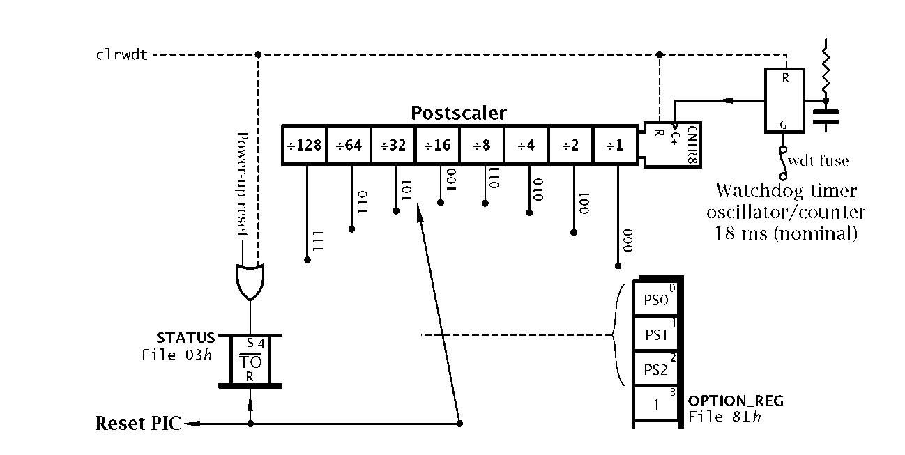
Fig. 13.1 The integral PIC Watchdog timer.
Rather than rely on external Watchdog timers, all PIC MCUs, even the early 12-bit PIC16C5XX family, have an integral module as illustrated in Fig. 13.1. A built-in oscillator separate from the processor clock runs continually if the Watchdog timer is enabled, with a nominal period of 18 ms. The integral capacitor/resistor timing network is not tightly specified and as a consequence the period will vary with device process, temperature and supply voltage from a minimum of 7ms (lowest temperature -40°C, highest VDD 6 V) up to a maximum of 33 ms (highest temperature +85°C, lowest VDD 2 V) – see Fig. 15.8.
The Watchdog oscillator is followed by an 8-bit Watchdog postscaler counter. This prescaler be set to give Watchdog counter overflow timeout periods going up in powers of two up to nominally 18 x 128 « 2.3s – 0.9 s minimum, 4.2 s maximum. The actual value is selected by the programmer using the PS[2:0] (Pre/Post Scaler rate Select) bits in the Option register (OPTION_REG) – see Fig. 13.2. The Watchdog postscaler and counter are both cleared with the clrwdt (CLeaR WatchDoG Timer) instruction and issuing this at regular intervals is the mechanism whereby the programmer prevents time-out.
Fig. 13.2 The Option register.
The Watchdog timer postscaler is a shared resource with Timer 0 (see Fig. 13.3) and cannot be used for both functions. The PSA (Pre/Post Scaler Assignment) bit is used to assign this resource either to the Watchdog timer or to Timer 0. On Reset the postscaler is assigned to the Watchdog timer and time-out is set to 128.
Even with this default assignment the programmer must enable the latter by setting the WDTE configuration fuse, as described in Fig. 10.5 for example:
Or the equivalent that is appropriate to your C compiler; for instance, in the CCS compiler:
If the Watchdog timer overflows it clears the![]() bit in STATUS[4] – see Fig. 4.5.This bit is set by the clrwdt or sleep instruction and on Power-on reset. clrwdt also sets the PD status bit. TO is cleared after Watchdog time-out has occurred; as listed in Table 10.3. It is not changed if the PIC is manually reset. TO is a read-only bit and therefore cannot be altered by the programmer other than by using clrwdt or by putting the MCU in its Sleep state.
bit in STATUS[4] – see Fig. 4.5.This bit is set by the clrwdt or sleep instruction and on Power-on reset. clrwdt also sets the PD status bit. TO is cleared after Watchdog time-out has occurred; as listed in Table 10.3. It is not changed if the PIC is manually reset. TO is a read-only bit and therefore cannot be altered by the programmer other than by using clrwdt or by putting the MCU in its Sleep state.
Unless the PIC is sleeping a Watchdog reset will force execution to begin at the normal Reset vector 000h. In some circumstances the programmer may want to distinguish between the two sources of reset. For example, assume that a system is counting cans of beans moving along a conveyer belt in the manner shown in Fig. 13.4, keeping a tally in a file register called BEAN_COUNT. On Power-on this tally is to be zeroed. If due to a glitch the PIC’s Watchdog times out and the PIC resets, then this tally should be left unchanged. To do this we can use code to check the state of TO and take the appropriate action; for instance:
Resetting initializes the Watchdog timer and zeros the postscaler so it’s not necessary to issue an extra clrwdt as we have done above. However, the initializing process will add to the time it takes to get into the normal main code and the normal loop clrwdt, thus an extra clrwdt at the end of any initializing code is useful insurance.
In the 12-bit PIC family the Watchdog time-out was the only way short of a Manual reset to awaken a device in the Sleep state. The sleep instruction resets the Watchdog and postscaler counters to give a full timeout period when entering the Sleep state. As the Watchdog oscillator is stand-alone it continues to run while the PIC is asleep. After the ordained period a Watchdog reset occurs and the PIC resumes execution with the instruction following sleep. If necessary the programmer can determine that the time-out occurred during the Sleep state by examining the TO bit.
The Watchdog awaken mechanism is not so important for the mid- and high-range PIC families. These can be awakened by an external interrupt, and where applicable the Timer 1 and Analog modules, both of which have the option of a self-standing clock oscillator. Where the watchdog is enabled and used in the Sleep mode the designer should be aware that the typical current consumption4 rises from typically 1.5 /A (24 / A maximum) to 10.5 / A (42 / A maximum). Where long-term battery operation is required, this presents serious problems. Running the processor continually at the lower frequency of 32.768 kHz with the Watchdog disabled takes typically 52/A (105 /A maximum) in comparison.
The original 12-bit PIC16C5XX family features a basic 8-bit counter/-prescaler which was called a Real-Time Clock/Counter. Although this term was still used in the early 14-bit PIC16CXXX data sheets, the introduction of additional timers lead to the more consistent term Timer 0 (TMR0).For example, the CCS C compiler sets the Timer 0 clock source to external low-going edge with a prescale value of 4 by calling setup_counters![]()
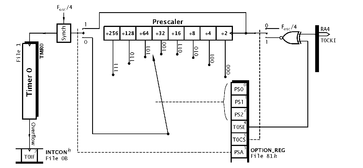
From Fig. 13.3 we see that Timer 0 comprises a primary 8-bit counter located at File 1 in tandem with an optional 8-bit prescaler counter. This gives eight selectable clock rates into the primary counter as selected by the three PS[2:0] bits in OPTION_REG. This Timer 0 prescaler is actually the same circuit as the Watchdog’s postscaler15 and PSA in OPTION_REG[3] must be set to 0 to assign the prescaler to Timer 0.
Fig. 13.3 Simplified equivalent circuit for Timer 0.
The prescaler is assigned to the Watchdog timer by default on Power-on/Manual reset and in this situation the primary counter is either clocked by the internal cycle clock Fosc at a rate XTAL/4 or from an outside source via the Timer 0 Clock Input RA4/T0CKI pin. The Timer 0 Clock Select T0SC bit at OPTION_REG[5] is used to select the internal/external mode. When clocked from outside, the active edge is set using the Timer0 Set Edge T0SE bit at OPTION_REG[4].
In order to synchronize the outside clock to the internal Timer 0 primary counter, a 2-stage shift register is used at the latter’s clock input. This causes a 2 x Fosc/4 delay; 1 is with an 8MHz crystal. Where the primary counter is directly connected to the internal clock, this will cause a 2-count delay before anything happens after a datum is written into Timer 0 at File 1. This synchronization is such that Timer 0 may be read from or written to in the normal way without interfering with any possible count action.
When the primary counter overflows![]() the
the
Timer 0 Interrupt Flag T0IF is set. This event can be sensed by polling INTCON[2] or if the Timer0 Interrupt Enable mask bit T0IE in INT-CON[5] is set an interrupt will automatically be generated – see Fig. 7.4.
An external clock signal going directly into the primary counter should be high for at least 2Tosc + 20 ns and low for at least the same time. Thus for a 8 MHz crystal, Thigh should be 270 ns and the same for T|0w; a maximum frequency of 1.8 MHz. When the prescaler is used this minimum total period of 4Tosc + 40 ns can be divided by the prescaler ratio. The input waveform is subject only to a minimum 10 ns pulse width. Thus with a ^256 setting, a nominally 50 MHz signal at T0CKI will be counted.
When assigned to Timer 0 the prescaler is not readable, so the timer is not strictly a 16-bit counter. Reading Timer 0 does not affect the prescaler but any instruction writing to it (eg. clrf 1, movwf 1) will both clear the prescaler and the clock synchronizer.
As the prescaler is assigned to the Watchdog on Power on/Manual reset it can be subsequently changed over by clearing PSA. However, it is possible that this change-over could cause a Watchdog reset even if it is disabled. Microchip therefore recommend that the change-over be preceded by a clrwdt instruction; for example:
The code shows the prescaler divides clock input by four from the T0CKI pin, and incrementing on the . It is also possible to change the prescaler over from Timer 0 to the Watchdog timer ‘on the fly’. In the same manner the clrwdt should be executed before altering OPTION_REG to avoid a spurious Watchdog reset.
Timer 0 is mainly used either to count external events or to determine the period between external events. it can also be used to time software toggling port pins for precisely known durations, without tying up the processor in time-wasting delay routines.
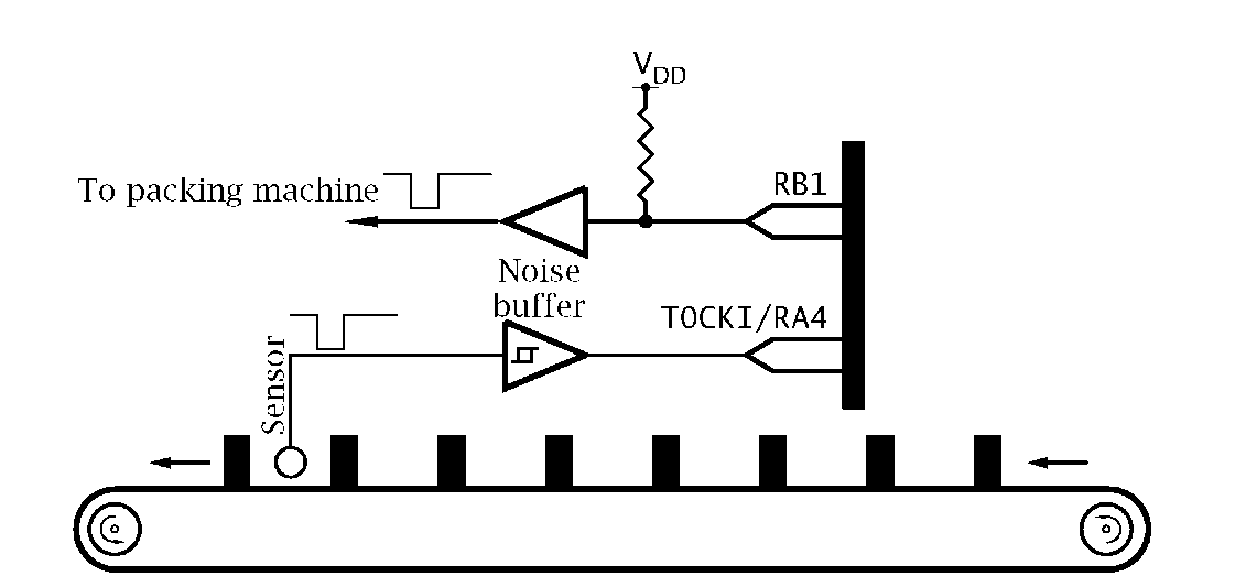
Fig. 13.4 Counting cans of beans on a conveyer belt.
We will illustrate the usage of Timer 0 as an event counter and stop clock with two examples. The first is to tally cans of baked beans travelling along a conveyer belt, as shown in Fig. 13.4. Each 24 cans passing the sensor is to generate a pulse to a packing machine, so that the box can be replaced by a new empty container. This pulse need only be a few microseconds in duration. A double-byte count is also to be kept of the number of boxes packed since the last Power-up/Manual reset. This will be uploaded to the central plant computer at the end of the shift for inventory control.
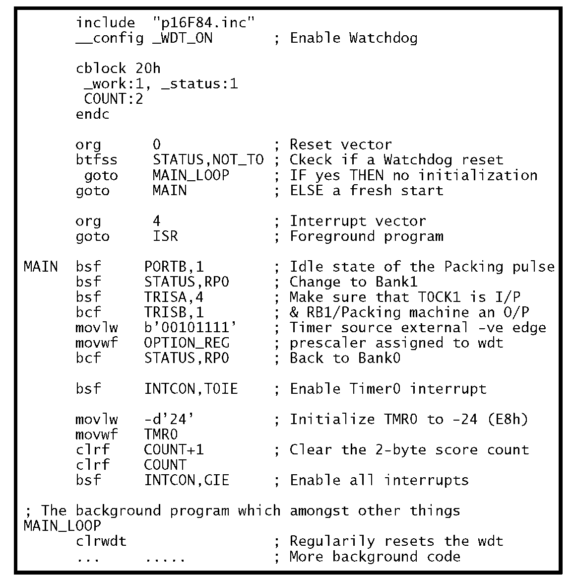
Our first consideration is the setup and initialization code. The code shown below begins by checking the TO flag at the Reset vector. If zero then the bulk of the initialization code is omitted as reset was due to a Watchdog time-out. If this was not the case then port pin RA4/T0CKI is set up as an input and RB1 set up as an output to activate the packing machine.
The Option register, also in Bank1, is set up to assign the prescaler to the Watchdog and extend its time-out period by x128. The Timer 0 counter is set to be clocked from T0CKI on a negative-going edge. Finally, back in Bank0 Timer 0 itself is set to E8h (i.e. -24 decimal) so that 24 can pulses will cause it to overflow and cause an interrupt. Both INTCON flags T0IE and GIE are then set to enable the interrupt.
The main background program commences with a clrwdt instruction. Provided that the background endless loop is no longer than 7 x 128 = 0.8961 s, the minimum Watchdog period, then time-out will not occur.


