To a computer or microprocessor, the world is seen in terms of patterns of digits. The decimal (or denary) system represents quantities in terms of the ten digits 0.. .9. Together with the judicious use of the symbols +, -and . any quantity in the range ±™ can be depicted. Indeed non-numeric concepts can be encoded using numeric digits. For example the American Standard Code for Information Interchange (ASCII) defines the alphabetic (alpha) characters A as 65, B = 66…Z = 90 and a = 97, b = 98…z = 122 etc. Thus the string “Microprocessor” could be encoded as “77, 105, 99, 114, 111, 112, 114, 111, 99, 101, 115, 115, 111, 114″. Provided you know the context, that is what is a pure quantity and what is text, then just about any symbol can be coded as numeric digits.1
Electronic circuits are not very good at storing and processing a multitude of different symbols. It is true that the first American digital computer, the ENIAC (Electronic Numerical Integrator And Calculator) in 1946 did its arithmetic in decimal2 but all computers since handle data in binary (base 2) form. The decimal (base 10) system is really only convenient for humans, in that we have ten fingers.3 Thus in this topic we will look at the properties of binary digits, their groupings and processing. After reading it you will:
• Understand why a binary data representation is the preferred base for digital circuitry.
• Know how a quantity can be depicted in natural binary, hexadecimal and binary coded decimal.
• Be able to apply the rules of addition and subtraction for natural binary quantities.
• Know how to multiply by shifting left.
• Know how to divide by shifting right and propagating the sign bit.
• Understand the Boolean operations of NOT, AND, OR and XOR.
The information technology revolution is based on the manipulation, computation and transmission of digitized information. This information is virtually universally represented as aggregrates of binary digits (bits).4 Most of this processing is effected using microprocessors, and it is sobering to reflect that there is more computing power in a singing birthday card than existed on the entire planet in 1950!
Binary is the universal choice for data representation, as an electronic switch is just about the easiest device that can be implemented using a transistor. Such 2-state switches are very small; they change state very quickly and consume little power. Furthermore, as there are only two states to distinguish between, a binary depiction is likely to be resistant to the effects of noise. The upshot of this is that both the packing density on a silicon chip and switching rate can be very high. Although a switch on its own does not represent much computing power; five million switches changing at 100 million times a second, manage to present at least a facade of intelligence!
The two states of a bit are conventionally designated logic 0 and logic 1 or just 0 & 1. A bit may be represented by two states of any number of physical quantities; for example electric current or voltage, light, pneumatic pressure. Most microprocessors use 0 V (or ground) for state 0 and 3-5V for state 1, but this is not universal. For instance, the RS232 serial port on your computer uses nominally +12 V for state 0 and -12 V for state 1.
A single bit on its own can only represent two states. By dealing with groups of bits, rather more complex entities can be coded. For example the standard alphanumeric characters can be coded using 7-bit groups of digits. Thus the ASCII code for “Microprocessor” becomes:
Unicode is an extension of ASCII and with its 16-bit code groups is able represent characters from many languages and mathematical symbols.
The ASCII code is unweighted, as the individual bits do not signify a particular quantity; only the overall pattern has any significance. Other examples are the die code on gaming dice and 7-segment code of Fig. 6.6.Here we will deal with natural binary weighted codes, where the position of a bit within the number field determines its value or weight. In an integer binary number the rightmost digit is worth 20 = 1, the next left column 21 = 2 and so on to the nth column which is worth 2n-1. For example the decimal number one thousand nine hundred and ninety eight is represented as 1 x 10³ + 9 x 10² + 9 x 101 + 8 x 100 or 1998.
Table 1.1: 7-bit ASCII characters.
In natural binary the same quantity![]() is
is![]()
Fractional numbers may equally well be represented by columns to the right of the binary point using negative powers of 2. Thus 1101.11 b is equivalent to 14.75. As can be seen from this example, binary numbers are rather longer than their decimal equivalent; on average a little over three times. Nevertheless, 2-way switches are considerably simpler than 10-way devices, so the binary representation is preferable.
An n-digit binary number can represent up to 2n patterns. Most computers store and process groups of bits. For example the first micropro-cessor, the Intel 4004, handled its data four bits (a nybble) at a time. Many current processors cope with blocks of 8 bits (a byte), 16 bits (a word), or 32 bits (a long-word). 64-bit (a quad-word) devices are on the horizon. These groupings are shown in Table 1.2. The names illustrated are somewhat de-facto, and variations are sometimes encountered.
As in the decimal number system, large binary numbers are often expressed using the prefixes k (kilo), M (mega) and G (giga). A binary kilo is 210 = 1024; for example 64 kbyte of memory. In an analogous way, a binary mega is 220 = 1,04 8, 5 76; thus a 1.44 Mbyte floppy disk. Similarly a 2 Gbyte hard disk has a storage capacity of 2 x 230 = 2,147,4 8 3,64 8 bytes. The former representation is certainly preferable.
Table 1.2: Some common bit groupings.
Long binary numbers are not very human friendly. In Table 1.2, binary numbers were zoned into fields of four digits to improve readability. Thus the address of a data unit stored in memory might be 1000 1100 0001 0100 0000 1010b. If each group of four can be given its own symbol, 0.9 and A…F, as shown in Table 1.3, then the address becomes 8C140Ah; a rather more manageable characterization. This code is called hexadecimal, as there are 16 symbols. Hexadecimal (base-16) numbers are a viable number base in their own right, rather than just being a convenient binary representation. Each column is worth 160, 161, 162… 16n in the normal way.5
Binary Coded Decimal is a hybrid binary/decimal code extensively used at the input/output ports of a digital system. Here each decimal digit is individually replaced by its 4-bit binary equivalent. Thus 1998 is coded as (0001 1001 1001 1000)BCD. This is very different from the equivalent natural binary code; even if it is represented by 0s and 1 s. As might be expected, arithmetic in such a hybrid system is difficult, and BCD is normally converted to natural binary at the system input and processing is done in natural binary before being converted back.
Table 1.3: Different ways of representing the quantities decimal 0…20.
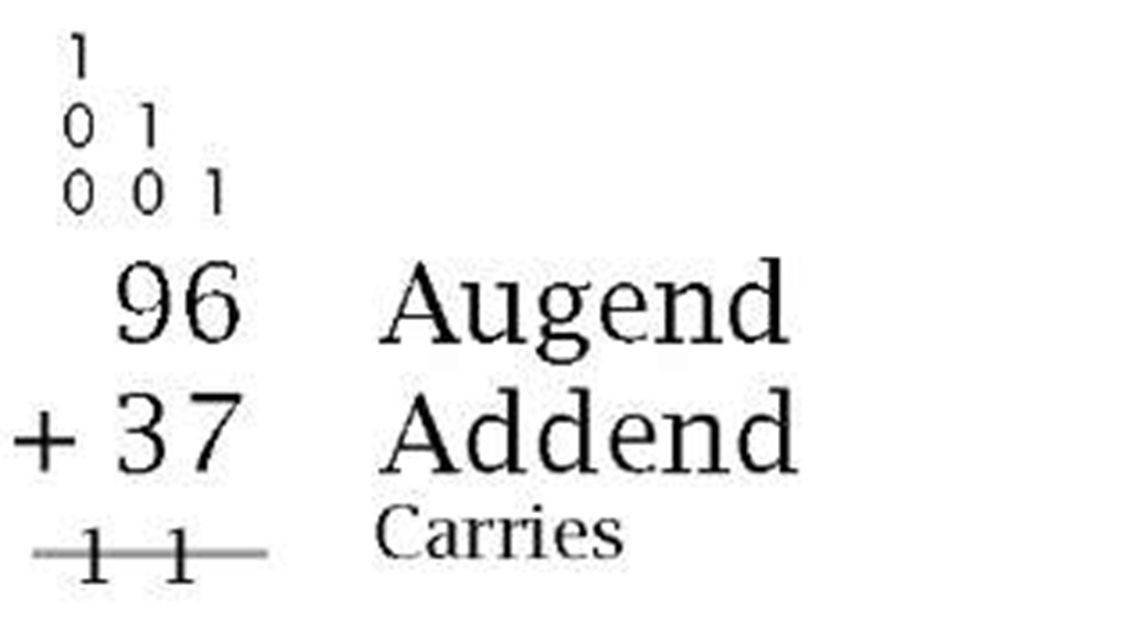
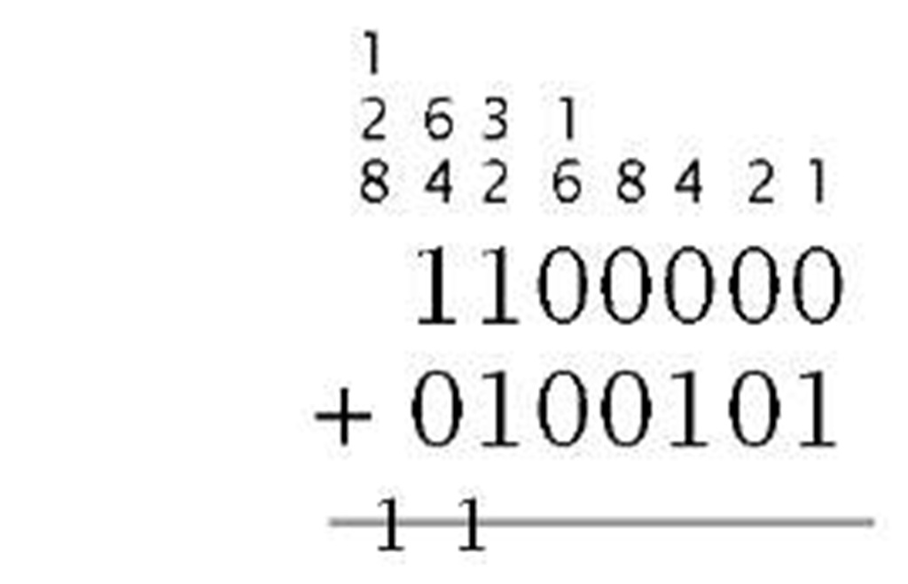
The rules of arithmetic are the same in natural binary6 as they are in the more familiar base 10 system, indeed any base-n radix scheme. The simplest of these is addition, which is a shorthand way of totalling quantities, as compared to the more primitive counting or incrementation process. Thus 2 + 4 = 6 is rather more efficient than 2 + 1 = 3;3 +1 = 4; 4 + 1 = 5; 5 + 1 = 6. However, it does involve memorizing the rules of addition.7 In decimal this involves 45 rules, assuming that order is irrelevant; from 0 + 0 = 0to9 + 9 = 18. Binary addition is much simpler as it is covered by only three rules: the most significant bit (MSB) column, its carry being the new MSD of the sum. For example:
Based on these rules, the least significant bit (LSB) is totalized first, passing a carry if necessary to the next left column. The process ends with
 |
 |
Augend Addend
Carries |
| 133 Sum | 10000101 | Sum |
| (a) Decimal | (b) Binary | |
Just as addition implements an up count, subtraction corresponds to a down count, where units are removed from the total. Thus 8 – 5 = 3 is the equivalent of 8 – 1 = 7; 7 – 1 = 6; 6 – 1 = 5; 5 – 1 = 4; 4 – 1 = 3.
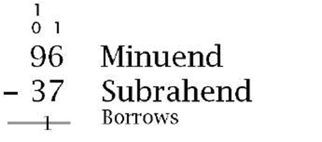
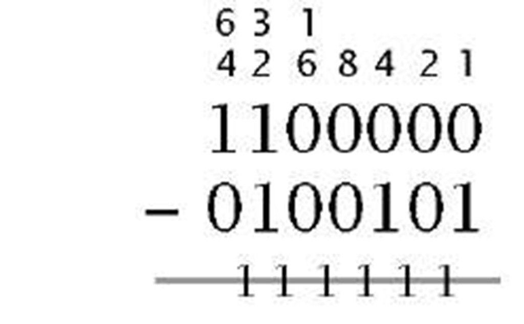
The technique of decimal subtraction you are familiar with applies the subtraction rules commencing from LSB and working to the MSB. In any given column were a larger quantity is to be taken away from a smaller quantity, a unit digit is borrowed from the next higher column and given back after the subtraction is completed. Based on this borrow principle, the subtraction rules are given by:
For example:
 |
 |
Minuend Subrahend
Borrows |
| 59 Difference | 0111011 | Difference |
| (a) Decimal | (b) Binary | |
Although this familiar method works well, there are several problems implementing it in digital circuitry.
• How can we deal with situations where the minuend is larger than the subtrahend?
• How can we distinguish between positive and negative quantities?
• Can a digital system’s adder circuits be coerced into subtracting?
To illustrate these points, consider the following example:
| 37 | Minuend | 0100111 | Minuend |
 |
Subtrahend |  |
Subtrahend |
| 41 | Difference (- 59) | 1000111 | Difference (-0111001) |
| (a) Decimal | (b) Binary |
Normally when we know that the when Minuend is greater than the Subtrahend, the two operands are interchanged and a minus sign is appended to the outcome; that is -(Subtrahend – Minuend). If we do not swap, as in (a) above, then the outcome appears to be incorrect. In fact 41 is correct, in that this is the difference between 59 (the correct outcome) and 100. 41 is described as the 10′s complement of 59. Furthermore, the fact that a borrow digit was generated from the MSD indicates that the difference is negative, and therefore appears in this 10′s complement form. Converting from 10′s complement decimal numbers to the ‘normal’ magnitude form is simply a matter of inverting each digit and then adding one to the outcome. A decimal digit is inverted by computing its difference from 9. Thus the 10′s complement of 3941 is -6059:
However, there is no reason why negative numbers should not remain in this complement form – just because we are not familiar with this type of notation.
The complement method of negative quantity representation of course applies to binary numbers. Here the ease of inversion (0 — 1; 1 — 0) makes this technique particularly attractive. Thus in our example above:
Again, negative numbers should remain in a 2′s complement form. This complement process is reversible. Thus:
Signed decimal numeration has the luxury of using the symbols + and – to denote positive and negative quantities. A 2-state system is stuck with 1 s and 0s. However, looking at the last example gives us a clue on how to proceed. A negative outcome gives a borrow back out to the highest column. Thus we can use this MSD as a sign bit, with 0 for + and 1 for -. This gives 1,1000111b for -59 and 0,01110011b for + 59. Although for clarity the sign bit has been highlighted above using a comma delimiter, the advantage of this system is that it can be treated in all arithmetic processes in the same way as any other ordinary bit. Doing this, the outcome will give the correct sign:
 |
 |
 |
 |
| (a) Minuend less than subtrahend | (b) Minuend greater than subtrahend |
From this example we see that if negative numbers are in a signed 2′s complement form, then we no longer have the requirement to implement hardware subtractors, as adding a negative number is equivalent to subtracting a positive number. Thus A – B = A + (-B). Furthermore, once numbers are in this form, the outcome of any subsequent processing will always remain 2′s complement signed throughout.
There are two difficulties associated with signed 2′s complement arithmetic. The first of these is overflow. It is possible that adding two positive or two negative numbers will cause overflow into the sign bit; for instance:
| 0,1000 (+8) | 1,1000 (- 8) |
 |
 |
| 1,0011 (- 13!!!) | 0,1101 (+3!!!) |
| (a) Sum of two +ve numbers gives -ve | (b) Sum of two -ve numbers gives +ve |
In (a) the outcome of ( + 8) + ( + 11) is -13! The 24 numerical digit has overflowed into the sign position (actually, 10011b = 19 is the correct outcome). Example (b) shows a similar problem for the addition of two signed negative numbers. Overflow can only happen if both operands have the same sign bits. Detection is then a matter of determining this situation with an outcome that differs. See Fig. 1.5 for a logic circuit to implement this overflow condition.
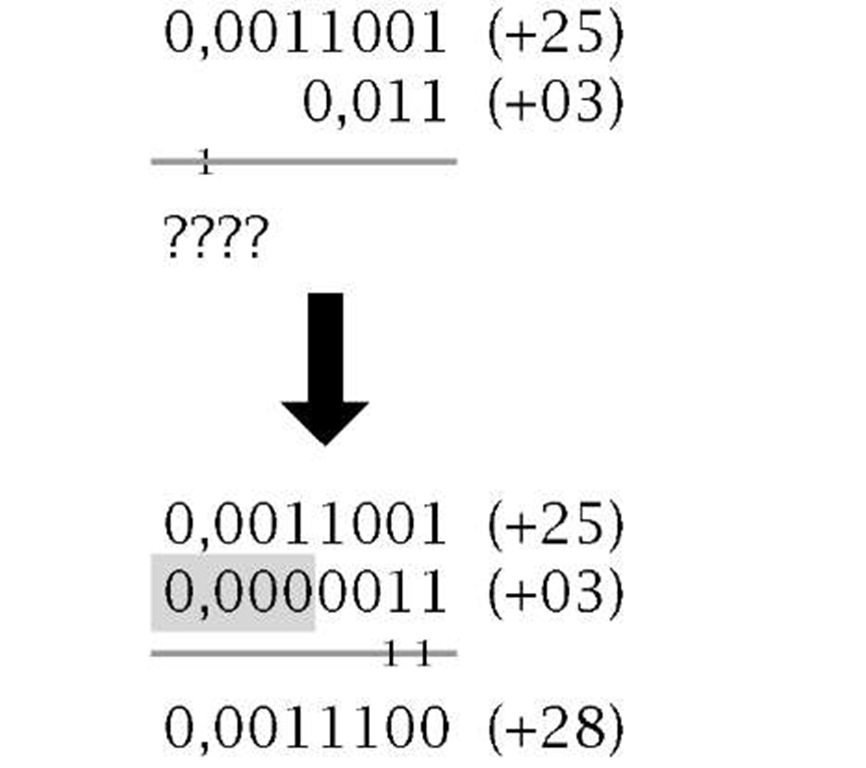
The final problem concerns arithmetic on signed operands with different sized fields. For instance:
 |
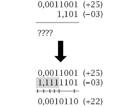 |
| (a) Extending a positive number | (b) Extending a negative number |


