Example 6.5
Write a subroutine to evaluate the square root of a 16-bit integer located in File 26:7h. The 8-bit outcome is to be returned in the Working register.
Solution
The crudest way of doing this is to try every possible integer k from 1 upwards, generating k2 by multiplication and checking that the outcome is no more than n. A slightly more sophisticated approach is based on the relationship:
On this basis a possible structure for this function is:
1. Zero the loop count
2. Set variable I (the magic number) to 1
3. DO forever:
(a) Take I from Number
(b) IF the outcome is under zero THEN BREAK out
(c) ELSE increment the loop count
(d) Add 2 to I
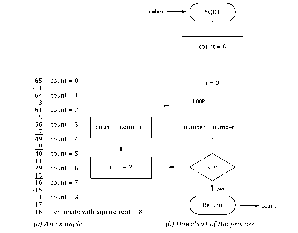
That is sequentially subtract the series 1, 3, 5, 7,9, 11.. .from Number until underflow occurs; with the tally of successful passes being the square root. An example giving V65 = 8 is given in Fig. 6.9(a) using this series approach. A flowchart visualizing the task list is also given in Fig. 6.9(b).
Fig. 6.9 Finding the square root of an integer.
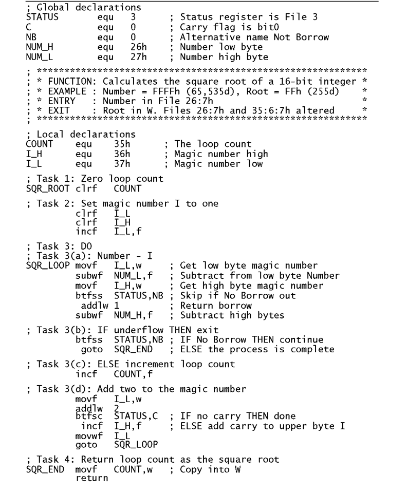
Program 6.11 Coding the square root subroutine.
The coding in Program 6.11 follows the task list closely. The maximum value of the loop count is FFh, as V65535 = 255. Thus a single byte at File 35h is reserved for this local variable. Similarly the maximum possible value of the magic number is 511 (1FFh) and so the two registers File 36:7h are reserved for this local variable. This of course means that Task 3(a) entails a double-byte subtraction. The coding is somewhat simplified as the high byte of I, that is I_H, is never more than 01 h and so a borrow from the lower byte can be added to a copy of I_H before the high-byte subtract to return the borrow without overflow. If a borrow is generated from this high-byte subtraction the outcome is under zero and the loop is exited. Otherwise COUNT is incremented and I augmented by two. Actually the latter is always twice COUNT plus one, so COUNT is not needed. Instead, on return the 16-bit value I can be shifted once right. This divides by 2 and by throwing away the one that pops out into the carry, effectively subtracts by one – I is always odd and so its least significant bit is always 1 . Try coding this alternative arrangement.
Example 6.6
Repeat Example 5.5, which multiplies a byte by ten, but using a software stack for data storage and parameter passing. You may assume that the multiplicand byte is in memory at File 46h.
Solution
The global declarations for the subroutine of Program 6.12 and calling procedure is:
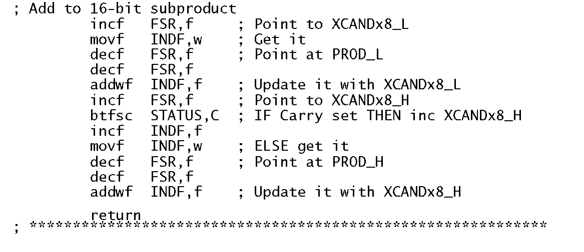
Program 6.12 uses the same technique as the original routine. First the multiplicand is shifted left once to multiply by two and then two further shifts multiplies by eight. The two resulting 16-bit data are then added to give the product. In the same manner as Program 6.6, the File Select Register is moved up and down to point the the appropriate datum as the program progresses. The double-byte product can be accessed relative to the Pseudo Stack Pointer by the caller. Unlike Program 6.6 this PSP is not altered when pushing out the multiplicand nor in the subroutine. This is because the subroutine is a dead end in that it can never call another subroutine. Thus a new stack frame need not be formed.
Program 6.12 Using a software stack to pass parameters and to provide a workspace.
Program 6.12 Using a software stack to pass parameters and to provide a workspace.
Example 6.7
In order to ensure that the 7-segment decoder subroutine of Program 6.4 does not cause the PCL register to overflow when the offset is added, a programmer has used the directive org to tell the assembler to locate the subroutine at the absolute instruction address 700h – as shown in Program 6.13. When the subroutine is tested by calling from another part of the program in the store somewhere lower than 700h the system fails and performs unpredictably. What has gone wrong?
Program 6.13 The software 7-segment decoder revisited.
Solution
The system goes berserk because on reset the PCLATH register is zeroed. Summoning the subroutine using call 700h the value of the PC becomes 0700h but the value of the PCLATH register remains unaltered. Later when the addwf PCL,f instruction is executed the full 13-bit Program Counter is updated with the bottom eight bits from the PCL register and the top five bits from the PCLATH register – as described in Fig. 4.3.Thus instead of the execution branching to one of the retlw instruction it will jump somewhere in Program memory in the area 0000 – 00FFh! This will happen even though adding the offset in W will not cause overflow of the PCL register, as was the original intention.
Even with this kludge the table is limited to 254 entries before the addition overflows the PCL register causing a malfunction. In any case it is considered bad practice for the programmer to specify the absolute location of sections of program code, as it is possible to overwrite code that the assembler places itself. Anyway with large programs it is error prone to try and keep tabs on the location of a myriad of modules. One way around the problems of both large tables and ensuring that the PCLATH register is correctly set, is for the caller to calculate the proper addition of the 13-bit value of the beginning of the subroutine SVN_SEG to the offset and place the top byte of the outcome in the PCLATH register. Of course the PIC is only capable of doing 8-bit arithmetic at a time and so we need to be able to find the values of both the bottom and top bytes of the label SVN_SEG. Fortunately the Microchip assembler has the directives high and low which can be used to dismember a 13-bit address to facilitate address arithmetic.
In the code segment above the address of the start of the table; that is SVN_SEG+1 is used, as this will be the value of the PC after the opening addwf PC,f instruction. Of course the org 700h instruction used in Program 6.13 can be dispensed with.
This code segment can easily be extended to deal with offsets which are greater than one byte by doing a double-byte addition to update PCL. As before only the lower byte of the offset is sent to the subroutine. In this way look-up tables of any size and located anywhere in Program memory can be implemented subject to the limited size of the Program store.
Self-assessment questions
6.1 Improve the accuracy of the 1-second delay Program 6.9 to within 0.2% by inserting nop instructions into strategic parts of the coding.
6.2 Create a subroutine that will read PortB every hour. You can base it on a 30-second version of Program 6.9. Say why this may not be a good use of the PIC’s resources.
6.3 Code a subroutine with the following specification:
• To divide a double-byte dividend by a byte divisor.
• Input DIVIDEND_H:DIVIDEND_L to be passed in File 2E:Fh.
• Input Divisor to be passed in the Working register.
• Output QUOTIENT_H:QUOTIENT_L to be returned in File 29:Ah.
• Output Remainder to be returned in W.
Use the subtract until underflow algorithm of Example 3.3.Comment on the problem of doing this division in this way.
6.4 Extend Program 6.4 to display A through F. Your solution can use a combination of lower and upper-case glyphs and should be robust.
6.5 Readings of the state of a mechanical switch can be erratic as the contacts will bounce for several milliseconds when closed, thus giving a series of 1 s and 0s. Similar considerations apply to electronic devices such as phototransistors when passing through a shadow. Although this problem can be fixed with hardware, it is usually more cost effective to use a software solution.
Devise a subroutine that will return with the stable state of a switch connected to Port B bit 7 as bit 7 of the Working register. Stability is defined as 5000 (1 388h) reads all giving the same value. The other bits of W are undefined.
6.6 An analog to digital converter is connected to PortB. Repeat SAQ 6.5 but this time defining stability as 1000 identical reads, and returning with the stable digitized analog voltage in W.
6.7 The subroutine in SAQ 6.6 returns the stable value of a noisy digitized signal, assuming 1000 identical values. Using this subroutine, code a main routine that will generate how this stable reading differs from a previous value previously stored in location File 40h. Each bit that differs is to be logic 1. Generate the position of the rightmost change bit in File 41 h.
6.8 The subroutine of SAQ 6.6 will not return a value when relatively high-frequency noise is present on the analog signal, as the resulting digital jitter will ensure that 1000 identical readings rarely occur. As an alternative, noise reduction can be obtained by taking the average of multiple readings. If the noise is random then n readings will give a noise improvement of -Jn. Devise a subroutine that will read Port B 256 times and return the 8-bit average in W for an increase in signal to noise ratio of 16.
![tmp18388_thumb[2][2]_thumb tmp18388_thumb[2][2]_thumb](http://what-when-how.com/wp-content/uploads/2011/06/tmp18388_thumb22_thumb_thumb.png)


![tmp18392_thumb[2][2][2] tmp18392_thumb[2][2][2]](http://what-when-how.com/wp-content/uploads/2011/06/tmp18392_thumb222_thumb.png)


![tmp18396_thumb[2][2][2] tmp18396_thumb[2][2][2]](http://what-when-how.com/wp-content/uploads/2011/06/tmp18396_thumb222_thumb.png)
![tmp18397_thumb[2][2][2] tmp18397_thumb[2][2][2]](http://what-when-how.com/wp-content/uploads/2011/06/tmp18397_thumb222_thumb.png)
