PATTERN
Returns one of eight energization patterns corresponding to the field vector as listed in Table 11.2. The mechanism of this look-up table coding has been described in Program 6.4.As this suite of subroutines originates at 050h, the 8-bit addition to the Program Counter will not result in roll over across boundaries. DELAY_10MS
This subroutine gives a nominal 10 ms delay independent of the processor crystal frequency, as defined by the programmer in the program header as a number FREQ in steps of multiples of 100 kHz. Thus for a 8 MHz crystal, giving a 2 MHz machine cycle, FREQ should be defined as 80 using the #define directive, before the program is assembled.
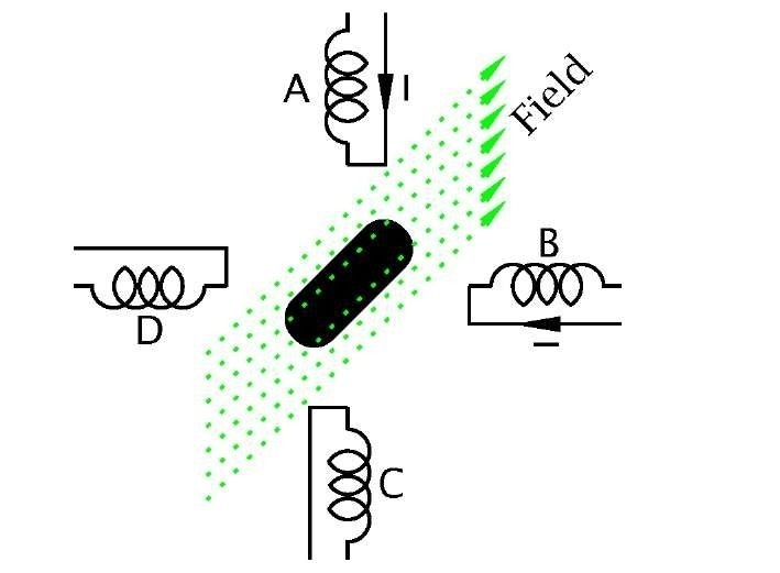
Fig. 11.12 The stepper motor.
The core of the subroutine is a loop needing a nominal 10 ms execution time at a crystal frequency of 100 kHz – 40 ^s machine cycle. This loop is transversed FREQ times. Thus our 8 MHz example will have a loop execution of 80 ms but will be executed 80 times to give our required 10 ms delay.
Example 11.4
Redo the keypad driver of Program 11.1 but coded in C.
Solution
Software structures of this nature, that is interacting with peripheral devices, are classified as device drivers. Device drivers or handlers have to be able to get at individual register bits in an efficient and sometimes real-time manner. Thus, even in a software system coded in a high-level language, the device drivers are traditionally written at assembly level. However, it is possible to code most device drivers in C, especially where response time is not critical.
The essence of the use of C in interacting with the various peripheral interface devices lies in its ability to operate at the colloquially called bit twiddling (or bit banging) level. To do this the programmer must be able to access fixed addresses in the Data store and to monitor or change individual bits within a datum.For example, the definition:
defines the name PORT_B as synonymous with the contents of File 6, that is PortB.
Any bit or bits in, say, Port B can be monitored by using the & AND operation; for example,executes the statement {do this;} if bit7 is zero and {do that;} if bit 1 of Port B is a one.
Most microcontrollers have native instructions to bit twiddle single bits directly in memory in a single execution cycle. Where only one bit is involved this is more efficient than the use of AND and OR operations, and because of this C compilers designed to be used for such hardware targets usually have (non standard) operators designed to make use of this feature.
The CCS compiler #bit declaration was used to define individual bits that could subsequently be tested by code. Using this technique our example becomes:
The CCS compiler comes with a header file for each processor which includes a bit description of all that device’s Special-Purpose Register set and I/O pins. Our examples assume that we have included the file 16f84.h. Thus:
There is also a complementary output function; for instance:
The CCS compiler adopts the policy that the inner workings of the various peripheral devices should be as invisible to the programmer as possible. To this end the compiler comes with a rich set of internal functions to set up and use the interface features appropriate to the target device specified by the header file.
As an example of this philosophy, set_tris_b(0xF0).Similarly the internal function port_b_pu11ups(TRUE); is an alternative to setting the RBPU bit in the Option register.
The CCS compiler handles parallel I/O in several different ways. The #use fast_io(b) statement below leaves it up to the programmer to explicitly set up the appropriate TRIS registers. Other alternatives allow the programmer to ignore such minutia, but then the compiler will set up the port configuration each time it is used, even if that configuration remains unchanged from the last usage.
Program 11.6 assumes the following code as part of the main routine:
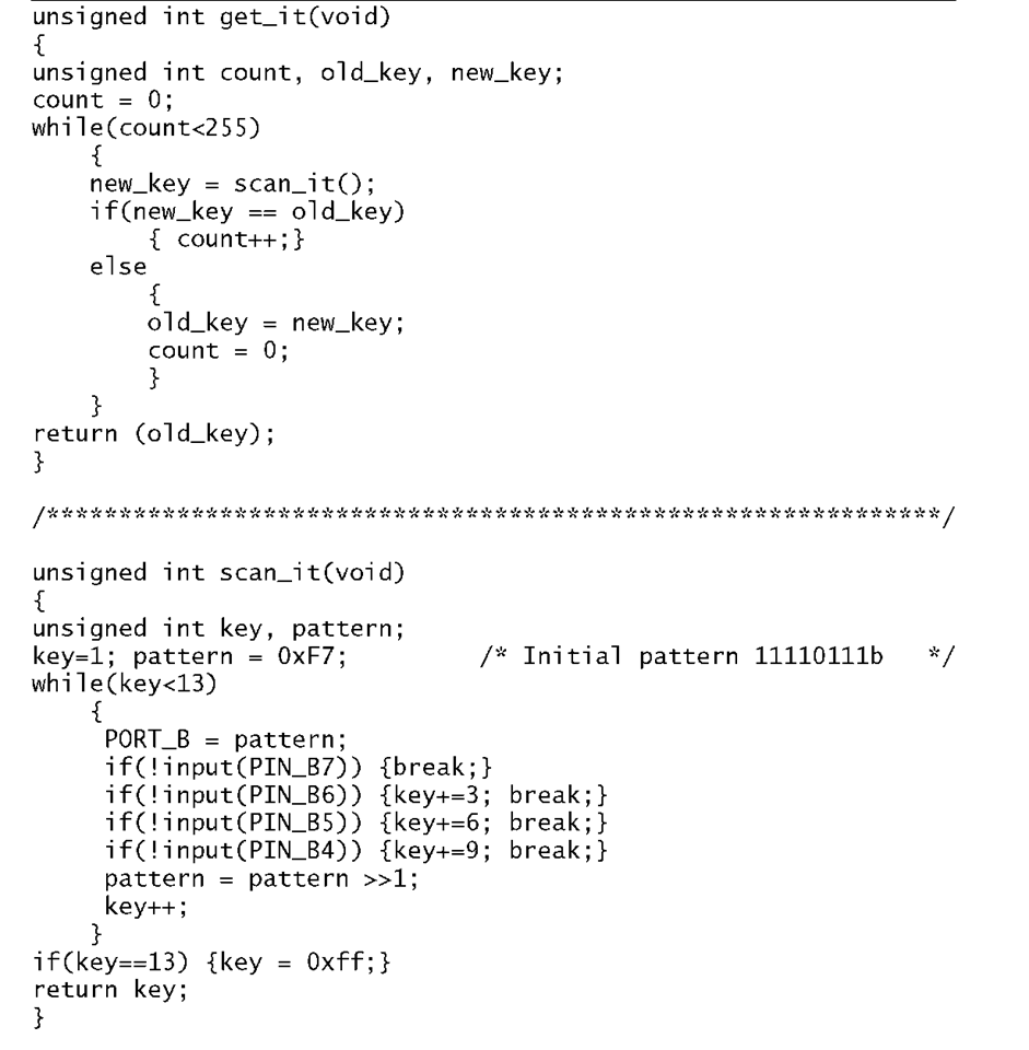
Program 11.6 Coding the keypad device driver in C.
The code in Program 11.6 shadows that of Program 11.1 in that two functions are used; scan_it() scans the keypad once and returns with a value 1 – 12 or FFh if no key is pressed. Function get_it() repetitively calls scan_it() until 255 identical values are returned, and this value is the final outcome.
scan_it() initializes the column count key to 1 and the column scan pattern to 11110111b. This test vector is sent to PortB and each row is tested in turn adding 3, 6 or 9 to the value of key if a zero is found and the while loop is exited (break). If after the four rows have been tested no outcome has been detected, the column scan pattern is shifted right and key is incremented. The process is continued until either a 0 is found or count reaches 13. In the latter case a key value of FFh (-1) is returned.
get_it() keeps a number of tries count tally, last reading o1d_key and current reading new_key variables. count is incremented after calling scan_it() if the current reading is the same as the last reading. If not, count is reset and o1d_key is updated. The while loop exits if count reaches 255 (the maximum value of an int variable), indicating that the last 255 readings are the same.
Example 11.5
Despite the increasing use of liquid-crystal alphanumeric readouts, discrete 7-segment LED displays are commonly used to show up to six numerical digits. Such readouts are particularly effective in low ambient light situations and where large displays are needed.
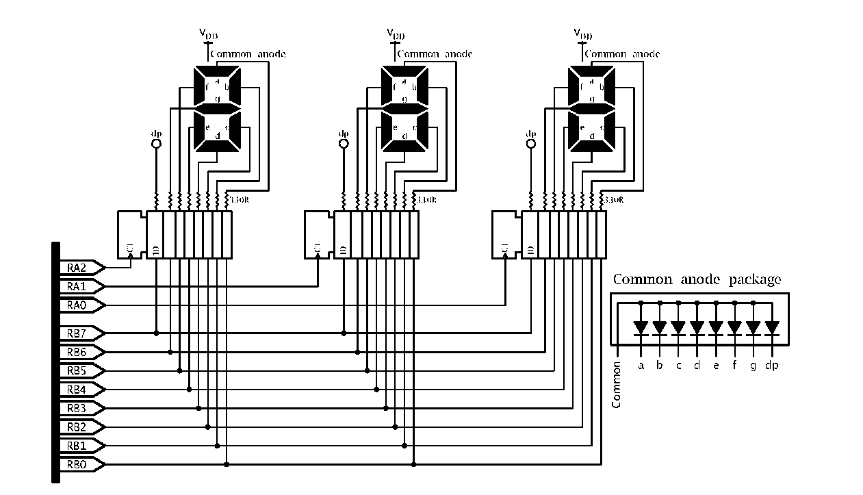
Fig. 11.13 Using port expansion to drive three 7-segment displays.
Assuming each display requires eight lines (seven segments plus decimal point) then a budget of 8 x n parallel lines are required for an n-digit display. The straightforward solution to this problem is shown in Fig. 11.13, where a 3-digit display is driven from three parallel registers on a local bus, in the manner of Fig. 11.10. The principle can be extended to six or more digits using the appropriate number of registers.
Fig. 11.14 Scanning a 3-digit 7-segment array.
The displays shown in the diagram are common anode and the appropriate LED is illuminated when the register output is low, with the sink current limited by the series resistance. In practice most logic circuitry can sink more current into a low output as compared to sourcing current from high and because of this common cathode displays are less common. In some larger displays , eg. 5 cm (2″), several LEDs may be paralleled or in series in each segment. In this situation larger anode voltages and/or currents may be needed and suitable drivers required to buffer the register outputs.
An alternative approach, shown in Fig. 11.14, is frequently used with LED-based displays. Instead of using a register for each digit, all readouts are connected in parallel to the one PIC port. Each readout is enabled in turn for a short time with the appropriate data from the output port. Provided that the scan rate is greater than 50 per second (preferably greater than 100) the brain’s persistence of vision will trick the onlooker into visualizing the display as flicker free.5 Of course the current flowing through the segment must be increased to compensate for the mark:space ratio but LEDs are more efficient at larger current pulses and the reduction of series resistance need not be pro-rata.
Discuss the pros and cons of these two arrangements with particular reference to the tradeoff of software and hardware. Illustrate your answer by displaying the decimal equivalent of the binary byte in File 20h. For example if the contents of BINARY were FFh then the display should be![]()

![tmp9145_thumb[2][2]_thumb tmp9145_thumb[2][2]_thumb](http://what-when-how.com/wp-content/uploads/2011/06/tmp9145_thumb22_thumb_thumb.png)
![tmp9146_thumb[2][2]_thumb tmp9146_thumb[2][2]_thumb](http://what-when-how.com/wp-content/uploads/2011/06/tmp9146_thumb22_thumb_thumb.png)
![tmp9147_thumb[2][2]_thumb tmp9147_thumb[2][2]_thumb](http://what-when-how.com/wp-content/uploads/2011/06/tmp9147_thumb22_thumb_thumb.png)
![tmp9148_thumb[2][2]_thumb tmp9148_thumb[2][2]_thumb](http://what-when-how.com/wp-content/uploads/2011/06/tmp9148_thumb22_thumb_thumb.png)
![tmp9149_thumb[2][2]_thumb tmp9149_thumb[2][2]_thumb](http://what-when-how.com/wp-content/uploads/2011/06/tmp9149_thumb22_thumb_thumb.png)
![tmp9150_thumb[2][2]_thumb tmp9150_thumb[2][2]_thumb](http://what-when-how.com/wp-content/uploads/2011/06/tmp9150_thumb22_thumb_thumb.png)


