Solution
Microchip suggest two approaches to the context switching problem for cases where the ISR has to change banks and GPRs are bank specific. The first is to keep the background program in Bank0 at any point of the code where the interrupt is enabled. Access to another bank can of course be made indirectly using the INDF file register.
The alternative approach is to save the Working register in whatever bank the interrupt occurs, but the Status register always in BankO. When STATUS is retrieved at the end of the ISR, the entry bank state (that is RP1:0 in STATUS – see Fig. 5.1 ) will be restored and the Working (and any other saved) register can then be pulled in from the bank they were actually saved in.
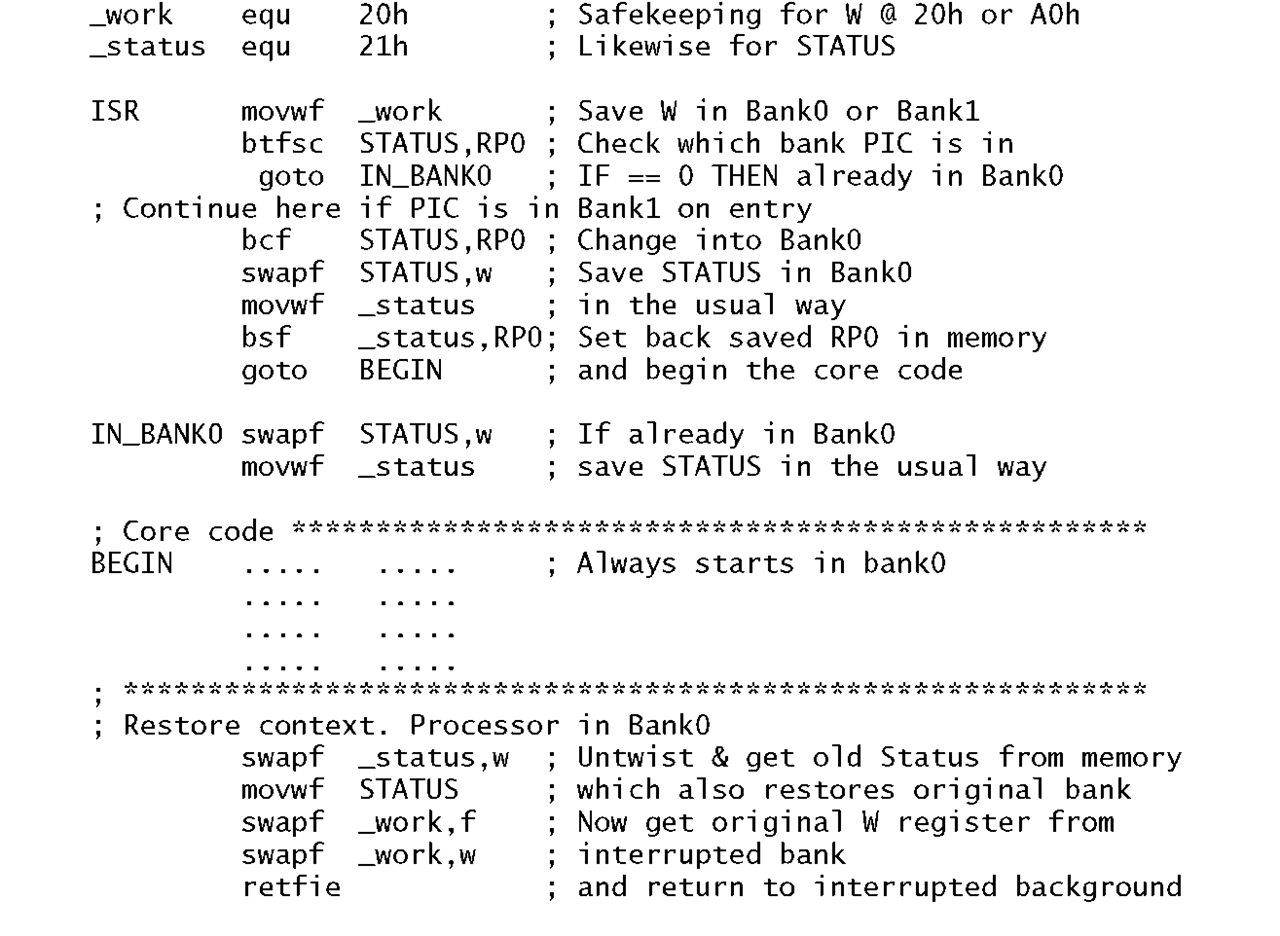
Program 7.4 uses this approach with context change entry and exit routines making no assumptions concerning the entry bank and which enters the core of the ISR code always in BankO. Here on entry the state of the Working register is copied into memory in the usual way ignoring the bank in which the processor enters. Although we have defined _work in the assembler as File 20h, if the PIC is in Bank 1 on entry the copy will actually be made at File A0h.
The next step is the more complex and depends on the entry bank state.
BankO
If the PIC is in BankO, as determined by the state of the Status register’s RP0 bit, then STATUS is copied into memory at file register _status in the normal way using the two instructions at IN_BANK0.
Bankl
If the PIC is in Bank 1 (i.e. RP0 is logic 1) then RP0 is cleared thus moving the processor to bankO. STATUS is then copied in Data memory at File 21 h, that is _status. Before entering the core code, bit 5 of File 21 h is then set to logic 1, restoring the copied version of the original state of RP0 out in memory. This means that on exit when STATUS is restored the PIC will move back into Bank 1.
The core code is always entered with the PIC in BankO. At the end of this code the programmer must ensure that the processor is back in BankO. In this situation restoring the context is done in the normal way, with STATUS being brought back from _status in Bank O. With this done,the PIC is now in its original Bank state and W can be restored in the usual manner from whatever bank it was stored. As this could either be in File 20h or File AOh then neither file should be used for any other purpose in the ISR to avoid inadvertent corruption.
Program 7.4 Saving and restoring the context for the PIC16C74 processor.
Example 7.4
Write a ISR to add one onto the array of file registers holding the four time bytes on each 0.1 s interrupt. Each byte location is to hold its data in a packed binary-coded decimal (BCD) format and a 24-hour time representation is to be adopted.
Solution
Each time the PIC enters the ISR one Jiffy must be added to the array of bytes HOURS:MINUTES:SECONDS:JIFFY. The base of each byte count differs in that JIFFY rolls over at a count of ten (i.e. modulo-10), SECONDS and MINUTES have a modulo-6O count and HOURS is modulo-24. Based on this scenario we have as a task list:
1. Add one onto the JIFFY count.
2. IF this gives 10 THEN zero JIFFY and add one onto the SECONDS count; ELSE goto EXIT.
3. IF this gives 60 THEN zero SECONDS and add one onto the MINUTES count; ELSE goto EXIT.
4. IF this gives 60 THEN zero MINUTES and add one onto the HOURS count; ELSE goto EXIT.
5. IF this gives 24 THEN zero HOURS.
6. EXIT
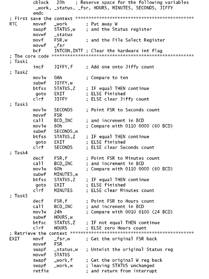
Coding for this task list is given in Program 7.5. Saving and restoring the context is implemented in the normal way. However, as the File Select Register (FSR) is used in the core of the ISR, it too is saved in a spare file register and retrieved on exit.
Rather than using equ directives to specify the file registers for each of the time array elements and those used to save the STATUS, W and FSR registers I have used the cblock – endc directive (Code BLOCK -END Code block). cblock 20h followed by a list of label names allocates each datum to a successive file register until terminated by endc. Thus _work is allocated to File 20h up to Jiffy at File 26h. Apart from brevity, the main advantage of a single code block over individual equ directives is that when several program sections are concatenated, each with their own code block, the additional variables are simply added to the list. Such additional cblock directives do not specify an explicit start address.
The core of the ISR is sectioned as shown to follow the task list. After each incrementation, the base literal is subtracted from the datum. If they are equal, then the datum is zeroed and the next datum incremented. The alternative of checking the Carry/Not Borrow flag would implement this task if the datum was equal or higher than the base literal, btfss STATUS,C.4
The example specified that the datum format should be packed BCD. Thus, 59 minutes should be stored as 0101 1001 ^ or 59h. This means that the incrementation process has to preserve this BCD format. This can be done after a normal increment by checking that the least significant nybble has not gone above nine. If it has, then six is added to correct the situation. As no datum should be above 59 this process is not needed for the upper nybble – Example 4.3 gives a task list for a complete packed BCD increment.
As this process needs to be carried out four times (for all except the Jiffy byte which is never greater than nine) then it is best implemented as a subroutine. This is shown in Program 7.6. Here the FSR is pointing to the packed-BCD datum that has to be incremented. This datum is simply binary incremented in situ using Indirect addressing. It is then corrected as described. The subroutine assumes that the pointed-to datum is already in a packed-BCD format on entry; it does not convert a natural binary byte to BCD.
Program 7.5 Coding the real-time clock ISR.
Program 7.6 Incrementing a packed-BCD byte with maximum value of 99.
7.2 What changes to Example 7.1 would you have to make to allow for a maximum value in the oven of 1000?
7.3 Based on Fig. 7.1 design an ISR to perform the following tasks:
• Copy the 16-bit count into two GPRs labelled TEMP_H and TEMP_L.
• Deduct from the previous count reading located in LAST_COUNT_H and LAST_COUNT_L and place the difference in DIFFERENCES and DIFFERENCE_L.
• Update the previous count with the new count.
• Set a GPR labelled NEW to a non-zero value to signal the background software that a new reading is available. The background routine will clear NEW when it has processed the data.
7.4 The speed of a rotating shaft can be measured by using a coded disk to generate a pulse on each angular advance of 10°, which can be used to interrupt a PIC. If the top speed is 20,000 revolutions per minute, what is the absolute maximum duration of the ISR in this worst-case situation to avoid missing pulses? You may assume a crystal frequency of 4 MHz.
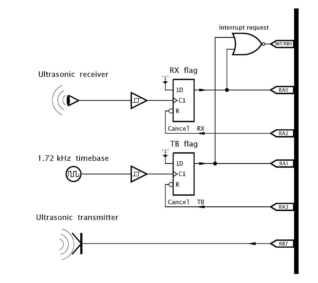
7.5 An electronic tape measure determines distance by pulsing an ultrasonic transmitter and detecting the time it takes for the echo return. The hardware for this echo sounder is shown in Fig. 7.6 and is based on that of Fig. 7.5.
The maximum range is specified as 2.5 meters with a resolution of 1 cm. The speed of sound in air is 344 meters per second at 2O°C, which gives a go-return time for one meter of 5.813 ms. Using a 1.72 kHz oscillator as a time base gives one interrupt per 5.813 ms; that is a Jiffy per cm.
Fig. 7.6 Echo sounding hardware.
Based on this hardware, the software must implement the following task list:
• Background routine
1. Zero Jiffy count and New flag.
2. Pulse the sounder.
3. Wait until New flag is non zero.
4. Display reading.
5. Repeat forever.
• Foreground routine.
1. IF oscillator THEN increment Jiffy count.
2. IF receiver THEN set New flag to non-zero to tell background program that the Jiffy count is the final value.
3. Repeat until neither is active.
4. Return
Code the foreground ISR tasked above using a GPR as a flag labelled NEW to tell the background program that the echo has returned and to read the Jiffy count as the required value. Use Program 7.3 as your model.
7.6 It is proposed to increase the range of the digital echo sounder to 10 meters and resolution to 1 mm. What change in the hardware and software would be required?
7.7 The system in SAQ 7.6 has been built and tested. However, readings seem to shift slowly with time. Oscillator drift is suspected but has been proven to be stable. Thinking laterally, one student wonders if the speed of sound varies with atmospheric conditions. After some research he arrives at the formula for temperature dependence as:
where V0 is the propagation velocity at 20°C and Vt is the velocity at a temperature of t. How much change in temperature At will there be to cause an error of 1 mm with the sounder measuring at its maximum range?


![tmp98_thumb[2] tmp98_thumb[2]](http://what-when-how.com/wp-content/uploads/2011/06/tmp98_thumb2_thumb.png)
