Assembling
The assembler program will scan the source file checking for syntax errors. If there no such errors the process goes on to translate to absolute object code; which is basically machine code with information concerning the location it is to be placed in Program memory. Syntax errors include such things as referring to labels that don’t exist or instructions that are not recognized. The output will include an error file giving any such errors. If there are no syntax errors, a listing file and machine-code file are generated.
In the case of our example the translation was invoked by entering:
where mpasmwin.exe is the name of the assembler program and root.asm is the specified source file. The flags are of the form /<option> and may be followed by + or – to enable or disable the option. Thus /e+ orders the production of an error file, /l + likewise for a listing file, /c+ makes labels case sensitive, /rhex specifies the default base radix to be hexadecimal. The flag /p16f84 tells the assembler to treat the source file as pertaining to the PIC16F84 device. mpasmwin can translate code for all PIC devices; whether for 12-, 14- or 16-bit cores.
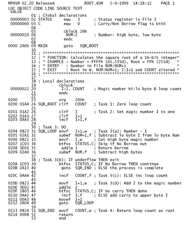
The listing file shown in Table 8.1 reproduces the original source code, with the addition of the hexadecimal location of each instruction and its code. The values of any symbols (such as NUM which is listed as File 20h) is also itemized.
The listing file also provides a symbol table enumerating all symbols/labels defined in the program. The memory usage map gives a graphical representation of Program memory usage. Any warning messages are embedded in the file where they are applicable. For example, if the destination operand w or f is omitted the assembler will default to the latter and embed a warning message at that instruction in the listing file.
This file has only documentation value and is not executable by the processor.
Executable code
The concluding outcome of any translation process is the object file, sometimes known as the machine-code file. Once the specified code is in situ in the Program store, it may be run as the executable program.
As can be seen in Table 8.2, such files consist essentially of lines of hexadecimal digits representing the binary machine code, each preceded by the address of the first byte location of the line. This file can be used by the PIC programmer to put the code into Program ROM memory at the correct place. As the location of each code byte is explicitly specified, this type of file is known as absolute object code. The software component of the PIC programmer reading, deciphering and placing this code is sometimes called an absolute loader.
In the MPU/MCU world there are many different formats in common use. Although most of these de facto standards are manufacturer-specific, in the main they can be used for any brand of MPU/MCU. The format of the machine-code file shown here is known as 8-bit Intel hex and was specified with the flag /a INHEX8M.
Let us look at one of the lines in root.hex in more detail.
Table 8.1 The listing file root.lst.
Listing
Table 8.1: The listing file root.lst.
The loader recognizes that a record follows when the character : is received. The colon is followed by a 2-digit hexadecimal number representing the number of machine-code bytes in the record; 10h = 16d in this case. The next four hexadecimal digits represent the starting byte address 0400h. This is twice the PIC’s Program store address of 200h, as each instruction takes up two bytes. The following 2-digit number is 00h for a normal record and 01 h for the end-of-file record – see the last line of Table 8.2. The core of the record is the machine code with each instruction taking two 2-digit hexadecimal bytes ordered low:high byte. The loader reads this lower byte first (eg. A4) and then ‘tacks on’ the upper byte (eg. 01 h) giving a 12-, 14- or 16-bit program word as appropriate to the target PIC core – eg. 01A4 for a 14-bit core clrf 24h.4 The final byte is known as a checksum. The checksum is calculated as the 2′s complement of the sum of all preceding bytes in the record; that is -sum. As a check-up on transmission accuracy, the loader adds up all received bytes including this checksum for each record. This received count should give zero if no download error has occurred.
Assemblers are very particular that the syntax is correct. If there are syntax errors5 then an error file will be generated. For example, if line 49 was mistakenly entered as:
got SQRLOOP then the error file of Table 8.3 below is generated.
Table 8.3: The error file
The assembler does not recognize got as an instruction or directive mnemonic and erroneously assumes that it is a label mistakenly not beginning in column 1. On this basis it assumes that SQRLOOP is an instruction/directive mnemonic and again does not recognize it.
Most assemblers allow the programmer to define a sequence of processor instructions as a macro instruction. Such macro instructions can subsequently be used in a similar manner to native instructions. For example, the following code defines a macro instruction called Delay_1ms6 that implements a 1 ms delay when executed on a PIC running with a 4MHz crystal. The directive pair macro – endm is used to enclose the sequence of native instructions which will be substituted when the mnemonic Delay_1ms is used anywhere in the subsequent program. The mnemonic will be replaced by the assembler with the defined code. Note that this will be in-line code unlike calling up a subroutine.
Where labels are used within the body of the macro, they should be declared using the local directive. This means that any conflict with labels where a macro instruction is evoked more than once is avoided.
This example is unusual in that the ‘instruction’ did not have any operands. Like native instructions, macros can have one or more operands. To see how this is done, consider a macro instruction called Bnz for Branch if Not Zero.7 Thus the instruction Bnz NEXT causes execution to transfer to the specified label if the Z flag is zero, otherwise continue on as normal. The definition of Bnz is:
Macros can be of any arbitrary complexity and can have any number of comma separated operands. For example, Microchip have available a large number of macros implementing arithmetic operations such as 16 x 16 and 32 x 32 multiplication. However, extensive use of macros can make programs difficult to debug, especially when an apparently simple macro instruction hides a number of side effects which alter register contents and flags. A frequent source of error is to precede a macro instruction with a skip instruction, intending to branch around it on some condition. As the macro instruction is in fact a structure of several native instructions, this skip will actually be into the middle of the macro – with dire consequences.
Macro definitions, whether commercial or/and in-house may be collected together as a single file and included in the user program using the include directive. Thus if your file is called mymacros.mac then the line at the beginning of your program include "mymacros.mac" will allow access by the programmer to all macro definitions in the file. The assembler will only generate machine code for any macro instructions actually used by the program. Any macros defined in the included file but not used will have no effect on the final machine code.
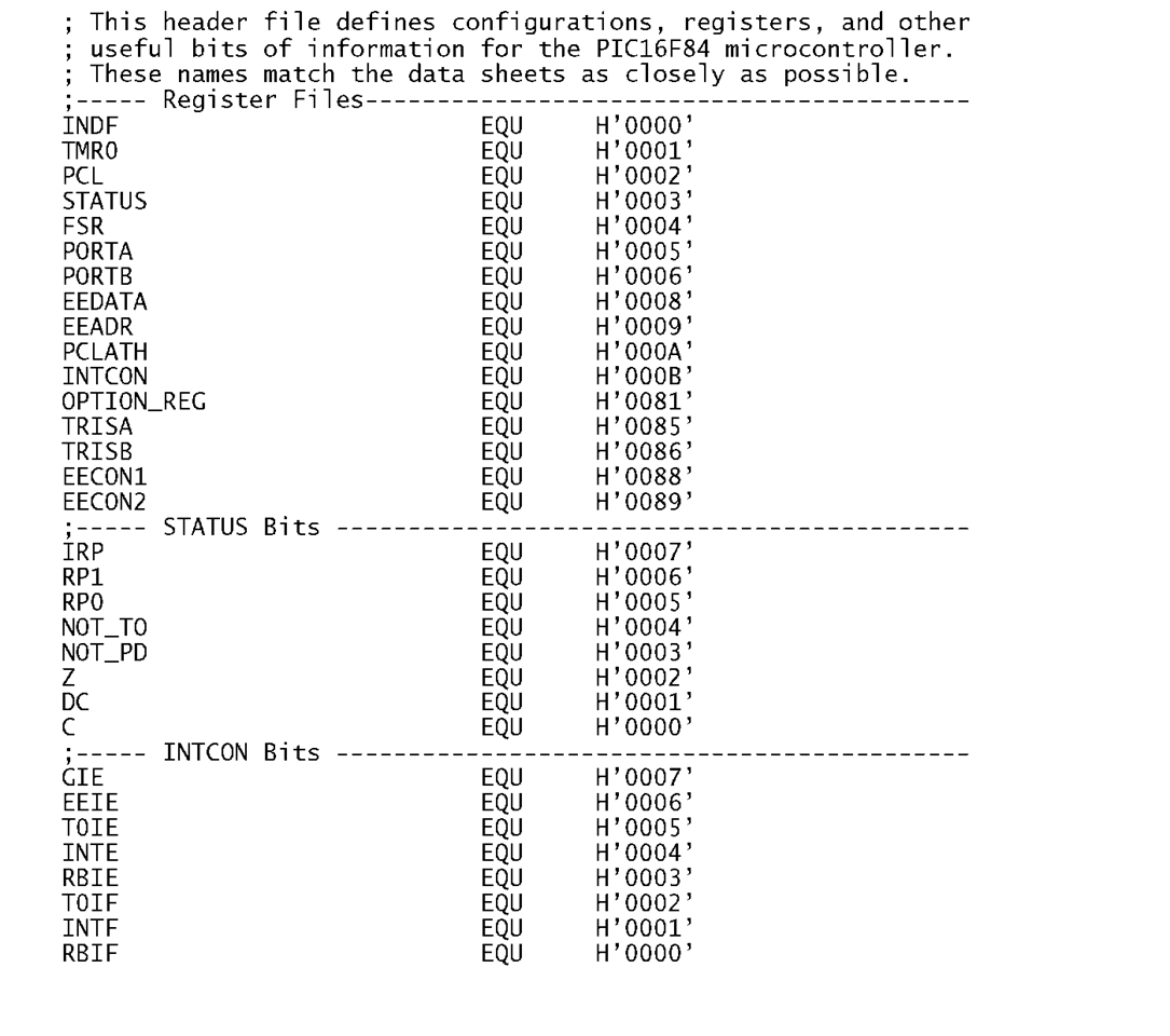
One of the major advantages of using an assembler over machine code programming is the use of names for the various file registers and bits therein; for example, INTCON instead of File0Bfo and GIE in place of 7. In code, such as Program 7.1. these equivalences are listed at the head of the source code using equ directives. Although the GPRs will have name labels unique to the particular program, the SPRs and their constituent bits are the same for all programs targeted to a particular type of PIC. Microchip provide files for each PIC, listing all SPRs and bits which can be included in the program’s heading; for example as used in Program 8.2. For instance, Table 8.4 shows the first part of Microchip’s file p16f84.inc which we will use for the rest of this text.
Table 8.4: Part of Microchip’s file p16f84.inc.
The process outlined up to here is known as absolute assembly. Here the source code is in a single file (plus maybe some included files) and the assembler places the resulting machine code in known (i.e. absolute) locations in the Program store. We stated earlier that where many modules are involved, often written by different people or/and coming from outside sources and commercial libraries, some means must be found to link the appropriate modules together to give the final single absolute executable machine-code file. For example, you may have to call up one of the modules that Fred has written some time ago. You will not know exactly where in memory this module will reside until the project has been completed. What can you do? Well a module should have its entry point labelled; say, FRED in this case. Then you should be able to call FRED without knowing exactly what address this label represents.
The process used to facilitate this is shown in Fig. 8.3. Central to this modular tie-up is the linker program, which satisfies such external cross-references between the modules. Each module’s source-code file needs to have been translated into relocatable object code prior to the linkage. "Relocatable" means that its final location and various addresses of external labels have yet to be determined. This translation is done by a relocatable assembler. Unlike absolute assembly, it is the linker that determines where the machine code is to be located in memory, not the programmer.
Treating the linker as a type of task builder, its main functions are:
• To concatenate code and data from the various input module streams.
• To allocate values to symbolic labels which have not been explicitly given constant values by the programmer – eg. using equ directives.
• To generate the absolute machine-code executable file together with any symbol, listing and link-time error files.
In order to allow the linker to do its job, it must have knowledge of the memory architecture of the target processor; basically where the array of general-purpose file registers start and end, where the vectors reside in Program memory and where the code begins and ends. In the case of Microchip’s mplink.exe linker this information is supplied in the form of a linker command file.
A simple example of such a command file for a PIC16F84 is given in Table 8.5. Three directives are used in the file.8
![tmp916_thumb[2] tmp916_thumb[2]](http://what-when-how.com/wp-content/uploads/2011/06/tmp916_thumb2_thumb.png)


![tmp921_thumb[2] tmp921_thumb[2]](http://what-when-how.com/wp-content/uploads/2011/06/tmp921_thumb2_thumb.png)
![tmp922_thumb[2] tmp922_thumb[2]](http://what-when-how.com/wp-content/uploads/2011/06/tmp922_thumb2_thumb.png)

