Introduction
In today’s highly mobile society, criminals often use vehicles to travel to and from the scenes of the crimes they commit. On many occasions, their vehicles track over surfaces which retain the impressions of one or more of the tires, leaving proof of their vehicles’ presence. These impressions range from a partial impression to a full set of tracks representing all four tires. Proper recovery of the impressions of track evidence, through crime scene drawing measurements, photography and casting, serves as a way of preserving the evidence for subsequent comparison with the tires and dimensions of a suspect vehicle.
Tire marks or tire impressions are those left by the tread design of a tire after they pass over a surface. As with any mark or impression, the detail retained by the surface ranges from exceptional to poor, depending on a variety of factors such as substrate qualities like texture and color, the amount and type of residue on the tire, moisture, etc.
Tire tracks are the marks or impressions left by the tires of a vehicle, exclusive of the tread design, and include track width, wheelbase, turning radius and the relative positions of the tracks of all four tires. Figure 1 gives some basic nomenclature.
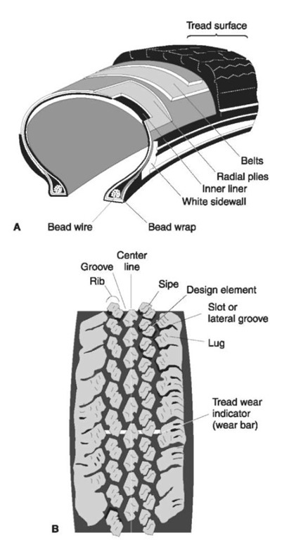
Figure 1(A) and (B) Radial tire: basic terminology.
Sidewall Information
Much information is molded into the sidewall. Portions of that information are of importance to the investigator and examiner, and should be noted when investigating or examining any tire. First noted should be the brand name and style name, such as Michelin XM+S 244 and the size of the tire, such as P 195 75 / R 14. Also of importance is the Department of Transportation (DOT) number, which will usually begin with the letters DOT. This is often on the serial side (inner side) of the tire. The DOT number will be similar to the following example:
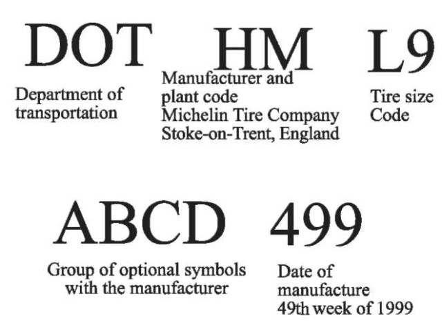
In this example, the two letters following the DOT number, such as HM, are symbols for the manufacturer and plant code. By looking this code up in a reference source, such as Who Makes it and Where, the specific plant in this example can be identified as the Michelin Tire Company, located in Stoke-on-Trent, England. The next letter and number are the tire size code. The following four letters, for example, ABCD, are optional and are manufacturers’ symbols. The last three numerical digits are important, as they indicate the week and year in which the tire was manufactured. For example, the numbers 499 in this example would indicate the tire was made in the 49th week (49) of 1999 (9). The last ’9′ could also indicate the tire was made in 1989 or 1979.
Tires that are retreads have a slightly different DOT number on them. The retread DOT number will begin with the letters DOTR of perhaps just R. The original DOT number that was on the new tire may be removed, or may be left undisturbed, so it is possible a tire will have both a DOT and a DOTR number on it. The DOTR number consists of three letters and three numbers and would be similar to the following example:

In this example, the three letters are a code to identify the retreading facility. A publication, Who Retreads Tires, lists approximately 5000 retreading facilities by their three letter code. The three numbers identify the week and year of retreading.
Tire Construction
There are three basic types of tire construction: bias, bias-belted and radial. A bias tire will have its plies running at a bias angle across the tire. A bias-belted tire will have the same plies, but will have the addition of a belt beneath the tread area. A radial tire will have the plies running in a radial direction, from bead to bead. Bias and bias-belted tires are less effective at reducing tire squirm, i.e. the degree of contraction of the tire tread while under load. Thus, an impression left by a bias or bias-belted tire may appear to have a more narrow appearance, and the grooves in the impression may appear more closed, than when looking at the static tire. Radial tires, because of the radial direction of their plies, reduce the amount of squirm, and result in almost no difference in dimension. In an examination, test impressions of the tire, made while on a vehicle, are necessary to provide a comparable standard for comparison with a crime scene impression.
Tires are built of many components, including a liner, sidewall components, the bead, plies, belts and tread rubber. These are assembled on a rotating and collapsible drum. After assembly of the components, the ‘green tire’, whose tread rubber contains no tread design at this point, is transferred to a mold. In the mold, under extreme heat and pressure, the tire components will be vulcanized and bonded together. A steam-pressured bladder will inflate inside the tire and press the green tire against the surfaces of the mold. It is here that the tread design and sidewall designs will be molded into the rubber.
Tire Designs and Databases
There are thousands of designs of tires, including those made for passenger vehicles, light, medium and heavy trucks, agricultural vehicles, off-the-road vehicles and motorcycles. Since the 1960s, the Tread Design Guide has offered a listing and photographs of most tire designs. An international version of the
Tread Design Guide is now available. This guide is published in hard copy form, but also in a more comprehensive version on a CD-ROM, which includes over 11 000 tire designs. It is subdivided by the type of tire category, i.e. ribbed tire, metric, lugged tire, etc., allowing for easier search on a PC computer format. These sources provide the investigator a method of linking a crime scene impression to a specific tire design and manufacturer. Once done, additional information of relevance can be sought from the respective manufacturer.
Some databases have also been created which contain various wheelbase, track width and turning radius data. These would enable entry of that data, as obtained from a crime scene, for the purposes of identifying potential vehicle types and brands.
Original Equipment Tires versus Replacement Tires
Original Equipment (OE) tires are those which are put on a vehicle when it is manufactured. Replacement tires are those which are purchased to replace the OE tires, or other replacement tires, when they wear out. A particular vehicle with its four OE tires will not be a rare occurrence, as many thousands of those vehicles would have been sold with the same design and size OE equipment. On the other hand, a vehicle with one or more replacement tires on it constitutes a much less frequent occurrence, as other vehicles of that type and brand are less likely to have the same brand and style replacement tires. A vehicle with three or four different designs of replacement tires in a particular size constitutes an occurrence that would probably not be repeated, owing to the large number of available designs and sizes.
Tire Size Designations
Tire sizes have been designated in a number of ways throughout the years. The tire size designations that have been used are shown below.
Older designations
Numeric: 6.45-14
6.45 = approximate section width in inches 14 = rim diameter
Alphanumeric: E R 78-14 E = load / size relationship R = radial tire 78 = aspect ratio 14 = rim diameter
Newer designations
Metric: 195R14
195 = approximate section width in millimeters R = radial tire 14 = rim diameter
T-Metric: P 195/75 R 14 P = passenger tire
195 = approximate section width in millimeters 75 = aspect ratio R = radial tire 14 = rim diameter
Aspect Ratio
The aspect ratio, otherwise known as the tire profile, is the relation of the height of a tire to its width. Appearance wise, a tire with a low profile or aspect ratio, such as 50, appears to look flatter and is proportionally wider, whereas a tire with a higher profile, such as 70, appears more conventional. Today, an increasing number of passenger cars are equipped with low profile tires to increase traction and performance.
Noise Treatment
As a tire goes through the stress cycle of contraction and expansion, the vibration of the individual design elements creates harmonics, or noise. Manufacturers attempt to treat and reduce this ‘noise’ by varying the pitch, or size, of the design elements as they are positioned around the tire. The sounds emitted by varied pitches creates better harmonics than the sounds emitted by the same pitch repetitively. This is referred to as ‘noise treatment’. Noise treatment may be as simple as creating three sizes of design elements, i.e. s, m and l (or 1,2 and 3). In cases such as these, the elements may follow a 1,2,3,1,2,3,1,2,3, etc. arrangement around the tire. Or, they may have an arrangement of those same three sizes, but in a more random order, such as 1,3,2,2,3,1,2,3,1,1,2,3,3,2,2,1 and so forth. In other cases, more complex and varied arrangements, including more than just three different sizes, may involve a pattern such as 1,2,3,4,4,3,2,1, 3,3,2,2,2,2,3,3,4,3,2,1,1,2,3,4, and so forth. An example of such an arrangement is illustrated in Fig. 2.In this example, the noise treatment consists of 64 design elements of four different sizes. They are arranged in four sequences, represented by models A, B, C and D. The six tread wear indicators are also included in Fig. 2. The lower part of the figure represents a crime scene impression. Note that only one possible area of the tire could have produced the noise treatment in that impression. This is because the portion of noise treatment for model A plus the portion of model D, as shown in Fig. 2, do not repeat elsewhere in the tire.
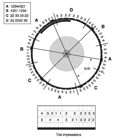
Figure 2 Noise treatment example.
In a non-directional noise treatment, the pitch sequence will be repeated on both sides of the tire. For instance, the following illustration shows how a tire, divided circumferentially at its center line, will have the same pitch sequence on each side. No matter which direction the tire travels in, it will leave an identical repeating sequence. Examination of a crime scene impression made by a tire with nondirectional noise treatment would not enable determination of the direction of the vehicle based on this alone.

A directional noise treatment has a pitch sequence that lays down a different sequence of noise treatment in each direction, relative to its direction of travel. An example of this is illustrated below. An impression made by a tire with directional noise treatment would enable a determination of the direction of the vehicle from the impression, as long as the position of the tire (left or right side of vehicle) and the way the tire was mounted on the wheel (which side is out, which side is in) was known. Directional noise treatment should not be confused with a directional tire, which must be mounted in a prescribed way and whose direction can be visually distinguished.

The noise treatment of tires is used during the examination of tire impressions, to assist in locating the possible position, or positions, of the tire that could have made a particular impression. An average passenger or light truck tire may have 2 m or more of tread in a full circumference impression. A crime scene photograph or a cast of a tire impression may only be 0.25-0.5 m in length. That crime scene impression represents only a small portion of the tire that made it. If the impression is short and the noise treatment is repetitive around the tire, there may be several locations on the tire that match the noise treatment in the questioned impression. Each will have to be examined closely for further evidence of wear and acquired characteristics. Recovering longer segments of impressions at crime scenes allows for a more specific determination of the portion(s) of the tire that made the impression.
Every examiner who conducts forensic tire impression examinations should be knowledgeable about tread design noise treatment and how it is significant in the comparison process.
Tread Wear Indicators
Tread wear indicators, also known as wear bars, are required in tire manufacturing. They must appear at least six times around the circumference of all tyres. They consist of rubber bars which are raised 2/32nds of an inch (0.16 cm) above the base of the grooves. In this way, as the tire wears down, the wear indicators will appear as bald strips across the remaining tread design. Tread wear indicators are visible in a two-dimensional impression if the tire is worn down to that level. They are also visible in three-dimensional impressions. Tread wear indicators, because they occur six times around a tire, appear in different portions among repeating noise treatments. For instance, a tire with a noise treatment that repeats four times will have six tread wear indicators in it. Each tread wear indicator will therefore be in a different portion of the noise treatment arrangement (Fig. 2). This can be of further assistance in locating the precise portion of the tire that made the impression.
Known Standards of Tires
Known standards of tires fall into two different categories. They include those obtained for tires that differ in design from the questioned impression, and can therefore easily be eliminated, and those that are similar in design and must be exhaustively compared with the impression with regard to the characteristics of tread design, dimension, wear and individual characteristics.
For those that fall into the category of being of different design to the questioned impressions, elimination standards need only consist of a photograph or adhesive lift of a short segment of the design. In addition, the sidewall brand name and style and size should be noted, as well as what vehicle the tire is associated with.
If the tire is similar in design to the questioned impression, the actual tire is required. When is it seized from the vehicle, its position on the vehicle (left front, right rear, etc.) and the side of the tire facing out (white wall side or black wall side) should be noted and should be marked directly on the tire before it is removed from the vehicle. To assist in the comparison process, full circumference known impressions of the tire must be obtained to assist in that comparison process. This is accomplished with inks or powders on long pieces of solid core chart board, or on clear polyester film placed over the chart board. This may be done on the actual suspect vehicle, or on a vehicle which will accommodate the tire.
Cases involving large trucks or trailer rigs should utilize those trucks or trailers when obtaining the known impressions. Tires should not be removed from any trucks that have double tires mounted on each side if they are to be compared with double tire impressions from the scene of the crime. Only after adequate known impressions are taken should they be removed for a more detailed examination. This is because the relative position of the tires to one another, as they have been mounted, is highly significant. Removal of the tires would lose that important aspect of the evidence.
Examination of Tire Impressions
Forensic examination first evaluates the general class characteristics of the tread design and dimension. If the tread design of the questioned impression is different from a particular tire, that tire can be eliminated. If the tread design is similar, a more detailed examination continues and requires full circumference impressions of that tire. With the full circumference impressions, the specific tread design and its dimensions, including agreement or disagreement of the noise treatment, can be compared. This examination may include superimposition of the known impression over the questioned impressions. This assists in locating the specific design, size and noise treatment features, as well as characteristics of wear and individual characteristics. If the design, size and noise treatment correspond, further comparison of the tire or tires proceeds. Any wear characteristics, such as worn away tread pattern, sipes, irregular tire wear and tread wear indicators, will assist further in locating the possible area or areas of the tire.
Finally, any random individual characteristics, including scratches, tears, cuts, stone holds and sipe damage, that appear on the tires and are clearly evident in the impression are examined. Their presence on the tire is random in nature and results in a tire that differs from others of the same tread dimension and design. The presence of random individual characteristics will contribute toward, or be the basis for, identification of that tire as making the crime scene impression. Tires are very durable, but they do quickly acquire substantial wear and damage, making them highly individual. When sufficient detail of these features is retained in the questioned impression, positive identification is readily possible.
When making examinations between a crime scene tire impression and a suspect tire, a range of conclusions is possible. It can be concluded that a tire positively made an impression. This would occur when the crime scene impression and suspect tire correspond in design, noise treatment, dimension, condition of wear and also share some random individual features. In less conclusive examinations, it is still often possible to associate a crime scene tire impression as sharing significant features in common with the suspect tire, such as design, noise treatment, dimension and condition of wear. Because of the large number of possible designs and sizes and conditions of wear, particularly when dealing with replacement tires, this category of conclusion is still very significant evidence. Finally, substantive differences in class characteristics of size or design, in the noise treatment or significant differences in the condition of wear can contribute toward, or be the basis for, elimination of the tire.
Absence of random individual characteristics, either in the crime scene impression or tire, does not constitute a basis for nonidentification, for several reasons. The impression may not have retained sufficient detail to allow for examination of those areas, or sufficient additional mileage on the vehicle may have worn off old characteristics or it may have acquired new characteristics.
Vehicle Dimensions and Turning Tread design width
Tread design width, also known as ‘arc’ width, is the distance between the edges of the tire tread. This is sometimes difficult to measure, owing to uneven wearing of the tire, the incompleteness of the impression and other factors.
Track width (stance)
Track width, also known as ‘tire stance’, is the distance measured perpendicularly from the center of one wheel (or impression) to the opposite wheel (or impression). The track width of the rear wheels is usually different from that of the front wheels. The measurement is made more easily if the vehicle is traveling in a straight line. The front wheel measurement will change dramatically if the vehicle is turning and is therefore less reliable. The rear track, when turning, will still record accurately; however, the measurement must be made carefully, perpendicularly. If the substrate is uneven, or the impression does not record sufficiently, it is more difficult to measure either track width accurately. If a wheel of a different dimension is put on the vehicle, or if the wheel mounting changes, as in the case of mounting wheels in a reversed position, the track width for that vehicle will be changed.
The track width on trucks that have two tires mounted on each side is measured from the point that is the direct center between the two wheels on one side to the center of the two wheels on the opposite side. Should trucks of the same type, model and year be configured with different axles or different wheels, the track width will be changed. Track width and wheelbase measurements are illustrated in Fig. 3.
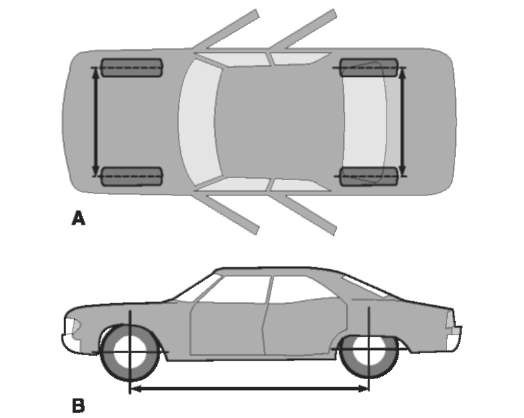
Figure 3(A) Track width: the dimension measured between the tire center lines at the ground. The front and rear track widths are not normally the same. (B) Wheelbase: the dimension measured longitudinally between front and rear wheel center lines.
Wheelbase
The wheelbase of a vehicle is the dimension measured longitudinally between the front and the rear wheel center lines. An equivalent to the wheelbase can be measured as the distance between the leading edges of the front and rear tire tracks, as in the case where the tires have sunk in the ground or have turned. Measurements should be taken from each side of the impression, as the leading edge of a tire, when turning, will cause this measurement to increase or decrease, depending on which side of the tire is used for the measurement.
Turning positions
Tires positioned on the rear of a vehicle, when the vehicle is turning, track to the inside of those tires positioned on the front. This is useful in reconstructing the position of tires at a crime scene and later linking similar positions to the respective tires. This is illustrated in Fig. 4.
Turning diameter
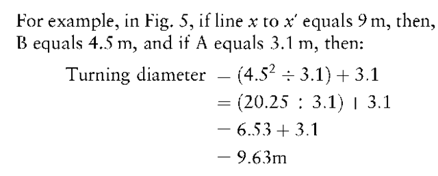
Every vehicle has a turning radius or turning diameter which represents the smallest radius that that particular vehicle type can turn in a circle. A crime scene impression with front wheel tracks that turn sharply can be measured and used to include or eliminate vehicles which can or cannot turn in that diameter or less. The measurement of the track should be made at its outer margin. The following formula and Fig. 5 illustrate this procedure.
Turning diameter =(B2 A)+ A
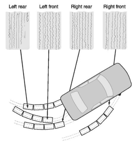
Figure 4 Turning positions. When the vehicle is turning, the rear tires track to the inside of the front tires.
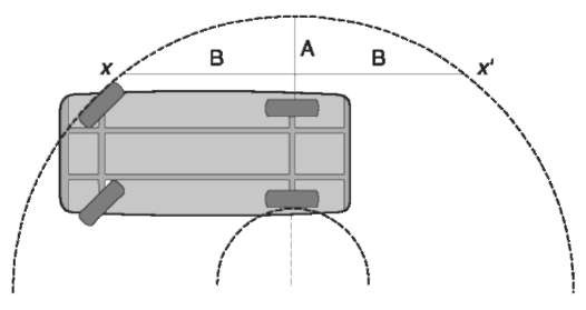
Figure 5 Turning diameter. Measurements are taken from the outer edge of the arc made by the outermost front tire. See text for details.
Recovery Methods Specific to Tires Photography
The general crime scene and examination quality photography of tire impressions at the scene of a crime is carried out in the same manner as for footwear marks, with one exception. That exception involves the need sometimes to document a long tire impression which is longer than that typically captured in a single examination quality photograph. This normally applies to impressions that are in excess of 0.5 m in length. Impressions longer than 0.5 m require a sequence of overlapping photographs, which upon processing and enlarging can be combined to recreate the long tire impression for comparison. To take sequenced photographs, a tape measure should be laid alongside the full length of the long impression. This measure, once laid down and once photography begins, should not be disturbed. It will not be used as a scale but only to help reconstruct the sequence and splice the photographs together. A second scale should be used and positioned in each individual tire impression segment photographed. That scale should be placed alongside, but on the same plane (level) as the bottom of, the tire impression. The photograph of each section should be approximately 0.5 m and overlap the previous photography by 6-10 cm. With this method, a long impression can be photographed in several segments, each accurately representing the respective section. The natural size enlargements of the segments can be assembled together to recreate the full impression. This method is illustrated in Fig. 6.
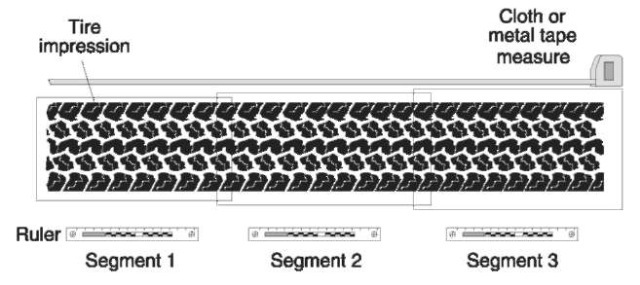
Figure 6 Documenting a long tire impression photographically.
Casting
Casts of three-dimensional tire impressions are invaluable for examination and should always be taken. They capture the contours and uneven qualities of the tire impressions, which are not always apparent or able to be recovered in photographs. In deeper impressions, sidewall treatments are often recorded, revealing potentially important information. For this reason, the casting material should be allowed to completely fill and overflow out of the tire impression. Because of the noise treatment, it is also desirable to cast the largest tire segment as is reasonably possible. Impressions that are 1 m or less usually pose no problem and should always be cast in their entirety. Larger casts can also be made, but as they increase in length, particularly if they are deep, their size and weight will rapidly become unmanageable. In cases involving long segments of one or more tire tracks from a vehicle, at least one cast, a minimum of 1 m long if possible, should be made of the best portion of each separate track. Additional casts, particularly of the more detailed segments of the tracks, should be considered, if possible. On the back of the cast, information about each impression and its relative direction should be noted. In addition, general scene photographs should be taken of the casts, once they are all poured but before they are lifted from the scene. This will also document the position and direction of the casts. Tracks made by trucks with two tires on each side, mounted side by side, should be cast as one two-tire unit. This will assure that a record of the exact relative position of those tires to each other is made.
Retread Tires
Retread tires account for a very large percentage of all tires made and sold. They are predominantly used on medium and large trucks, where the monetary savings between new tires and retread tires is significant. Some retread designs for truck tires closely simulate the original design.
Retread tires are made using one of two processes. Each of these processes leaves characteristics that reveal the tire is a retread and may also contribute to the individuality of the tire. They are known as the mold cured process and the precured process. The mold cured process uses strips of raw rubber that are applied to the used tire carcass, which is then placed into a mold, where the new tread is formed. The resulting tire is similar to a new tire. The precured process uses premolded rubber containing the tread design, which is then bonded to the original tire carcass. It will contain a splice joint, and in some instances two splice joints, which reveal where the precured tread rubber was joined together. The position of this joint will be different from most other retread tires of this design, and will be very significant should it be retained in a crime scene tire impression.
Retread tires for passenger vehicles are not made in the quantities that original molded tires are made. Their occurrence on a vehicle and in a crime scene tire impression may therefore be far less frequent and thus more significant. Information to support the frequency of a particular tire can be obtained by contacting the retreading facility, via the retread code on the tire. A retread Department of Transportation code, explained earlier, should be present on the retread tire, but occasionally this is omitted.
