Overview
Toolmark examinations form part of the physical comparative disciplines within the criminalistics branch of forensic science. The primary objective is to relate one physical object with another, by determining if a toolmark was made by a particular implement. Based on the concept that the implement has transferred a design or pattern to the marked surface, simple physical comparative examination techniques are employed. A determination that the transferred pattern contains both class and/or individual characteristics, will allow the examiner to report findings ranging from exclusion through to individual identity.
Definitions
A number of terms used in this topic are explained below.
A toolmark is defined as that mark left by the forcible contact of any implement with a softer surface. The nature and quality of the toolmark will be determined by:
• the character of the implement itself;
• the relative hardness of the two surfaces;
• the magnitude of the force applied;
• the relative motion of one surface over the other.
Multiple contact marks are those produced by such implements as saws, files, angle grinders, or even knives used in a sawing action. The use to which these implements are put is such that their working surfaces will contact the marked material on numerous occasions. While a considerable amount of useful information can be gleaned from the examination of such marks, normally only class characteristics can be identified.
Single contact marks on the other hand are those where the implement contacts the surface once on each application. It may be that the implement is applied to the surface on several occasions, but each application is a reflection of the implement’s working surface. As such, single contact tool marks are most suitable for identification work, and if individual characteristics are identified can often be reported as having been produced by a single implement to the exclusion of others of the same class.
Only two types of mark, the striated and the impressed toolmark, are produced by implements. Both types can be encountered in the one mark.
The striated toolmark is that mark left when lateral movement between the two contacting surfaces leaves a series of parallel striae (lines of ridges and valleys). (A good example of this type of mark, is a knife blade scraped across the surface of butter, leaving a contoured series of parallel lines indicative of the serrations of the knife blade.) The mark is produced as a result of a dragging or sliding motion, with minute imperfections existing on the contacting edge of the implement determining the depth and width of each striation left behind. The width, depth and number of these striae are generally quite individual and very diagnostic for the specific implement. While some implements, such as bolt cutters, axes or chisels, are designed to leave striated marks, many others can inadvertently leave such marks.
The impressed toolmark is produced when a hard object comes into forcible contact with the softer surface and no lateral movement occurs at the time of contact. Also described as depressed or compression marks, the features within such marks can be recognized as a negative ‘mirror’ image of that portion of the harder object that made contact. Such marks often include the transfer of minute (individual) imperfections present on the harder object.
Class or individual characteristics are the terms used to describe features identified within toolmarks.
Class characteristics are those features of a mark that identify it as having been produced by a specific type of implement. Often described as those provided by the original manufacturer of the implement, these class characteristics include features of size, general shape or profile, the type of cut or impression, and sometimes the direction of travel. Class characteristics are those generally retained throughout the working life of the implement.
Individual characteristics (also known as accidentals) are those features of a toolmark that are specific to the implement. Imperfections or irregularities on the surface of implements are (unintentionally) produced either at the time of manufacture or develop during subsequent use, abuse, corrosion or damage. Imperfections of this nature are random in nature and are subject to change over time. Some imperfections are large, such as when a chip of metal breaks off the tip of a screwdriver, most are microscopic, but all are unique to the implement.
Application in Criminalistics
If toolmarks are to be utilized to their full potential, investigators in general, crime scene investigators and crime laboratory personnel, all need to have a sound appreciation of the range of physical evidence to which this discipline may apply. The identification of both projectiles and cartridge cases (firearm identification) is recognized as a specialized toolmark examination discipline. The marks left by screwdrivers, crowbars or other implements used to force doors, premises, etc., axe marks in wood, the restamp-ing of vehicle engine numbers, the marks left by pliers, bolt cutters, knives, etc., the use of hammers, multi-grips and other implements, have all been the subject of toolmark identification work.
The definition of a toolmark, however, allows an even broader range of evidence types to be examined and reported on. By careful assessment, implements not normally associated with toolmark work (e.g. the marks left by teeth, the bumper bar of a vehicle or even a smear left by the edge of a shoe) could provide useful toolmark evidence. The range of impressed toolmark evidence is far broader than is often realized, and lateral thinking will often identify new applications. (The indentation left by a knee in the steel dashboard area of a vehicle allowed the crime scene investigator to nominate the person with the knee injury as the driver at the time of the accident.) (Recognizing that a heat sealer used in the production of drug deals might produce impressions on the plastic bags allowed a specific heat sealer to be identified; see Case study 6.)
Multiple contact marks Multiple contact marks, by their nature, will mask any individual characteristics, and examiners generally need to limit any identification findings to those relating to the class of implement. Examination of such marks may provide some initial assistance in certain investigations, but will generally have limited evidentiary value. (The width and sometimes the spacing of the marks left by a saw’s teeth may allow the examiner to exclude specific implements.) (In one case, marks left on the blade of an axe during sharpening were such that a coarse grinder rather than a sharpening stone was indicated. While clearly not able to identify the specific grinder, the examiner was able to demonstrate that the grinder in the defendant’s shed could produce marks similar to those on the axe.)
Single contact marks Almost any implement capable of leaving either an impressed or striated mark (or combinations of the two) should be considered as potentially capable of being identified. Extrusion marks produced on objects during manufacture are in fact striae left by the minute imperfections within the extruding tool. Such marks can be found on copper wiring, extruded plastics and even aluminum foil, and may be used to identify the origin of such evidence when located at a scene. (The extrusion marks on a plastic rubbish bag containing body parts were favourably compared with a carton of such bags in the possession of the defendant.)
To best illustrate the broad range of evidence types that lend themselves to toolmark identification the following illustrations, in the form of case studies, are provided.
Case study 1
The extrusion marks on the inner surface of flexible irrigation piping (used at a drug crop) was identified as originating from one end of a bulk supply at a local hardware store. The extrusion pattern consistently altered within a 10 m length (presumably at manufacture due to wear and dirt developing around the extrusion gate). This evidence corroborated statements identifying the suspect as having bought the piping, thus implicating him in the establishment of the drug crop (Fig. 1).
Case study 2
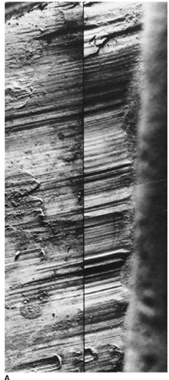
The gate to a car-wrecking yard was found to have had the chain cut. A suspect walking some 200 m from the gate was seen to place a pair of bolt cutters in the back of a utility vehicle as police drove past. A test cut made with the bolt cutters (in lead rod) showed a replication of the microscopic contours (striae) left on the cut chain link, sufficient to exclude any other implement (Fig. 2).
Case study 3
Several vehicles parked along a footpath had their tires damaged with a single stab into the tire sidewalls. A penknife was recovered from a young suspect, and test cuts produced in another inflated tire were matched to one of the stab marks. The striae in this case were very fine and compressed together (due to the angle at which the knife entered the tire wall) but clearly produced a unique and reproducible contour pattern. Duplicating the original angle and direction of travel was vital before a match could be demonstrated (Fig. 3).
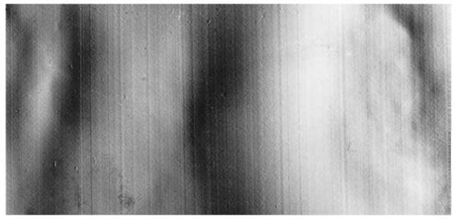
Figure 1 Case study 1. A cast of the inner surface of extruded irrigation piping. Extruded striae are quite common on a wide range of materials, including plastic bags, copper wiring, etc., and may allow a relationship to be demonstrated between two sites (objects). The major concern with such evidence relates to the length over which such comparable striae are left. A study of the manufacturing process and the quality controls in place, as well as samples from the manufacturer, should always form part of any such identification work.
Case study 4
The names stamped on the edge of a number of World War I medallions were suspected of having been forged. Sets of such medallions (in the name of specific war veterans) were being sold at auction as valuable collector’s items. The suspect was a jeweller who had three sets of very fine steel marking stamps. Test stampings produced in copper were compared with corresponding letters on the medallions. The use of the scanning electron microscope in this case allowed extremely detailed surface irregularities, which existed on the original stamps and which had been transferred to the medallions, to be used as a positive identification (Fig. 4).
Case study 5
Numerous small particles of steel recovered from the scene of a fatal parcel bombing were identified as belonging to a food can. Some of these fragments were recognized as forming part of the upper rim of the can, and minute, regularly spaced indentations along the side of the rim were identified as most likely to have been caused by the feeder wheel of an electric can opener. The marks exhibited a combination of ‘impressed’ and ‘striated’ detail created by the action of each individual tooth on the wheel digging in and pushing the can forward past the cutting wheel. Although 80% of these teeth marks were damaged by the close proximity of the blast (approximately 2 m of detonating cord had been wound tightly into the can), about 16 individual marks showed comparative detail. All 24 teeth on a feeder wheel of the electric can opener, recovered from a suspect’s home, left marks which could be clearly distinguished, one from the other. Requiring the development of new examination techniques (i.e. cleansing and preserving the ‘scene’ marks as well as producing undamaged ‘test’ impressions), subsequent comparison work identified that nine of the feeder wheel teeth could be compared with the 16 useable marks located on the bomb fragments. The subject of considerable research, the identification work confirmed that it would be highly unlikely for another feeder wheel to leave marks that would correspond in both detail and position to each other. The marks shown are two of the nine teeth marks which were compared (using a standard reflective light comparison microscope) and, although the scene marks have some distortion (due to blast effects on the metal), the distinct differences of one tooth to another can be readily seen (Figs. 5-7).
Case study 6
The examination of detail left on a heat-sealed edge of a small heroin deal allowed a specific heat sealer to be identified. The seals on the clear plastic bags needed to be cast on both sides before the ‘impressed’ marks could be examined in detail. Even when new, heat sealers leave distinctive features, and numerous drug trafficking operations have since been the subject of this type of identification (Figs 8-10).
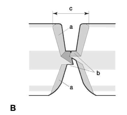
Figure 2 Case study 2. Bolt cutter identification. (A) Left, scene (chain link); right, test cut in lead. A classic striated tool-mark identification in which only a short segment of the cutting jaws were responsible. Identifications of this type can readily be applied to numerous similar implements such as pliers or wire cutters. (B) Cross-section sketch of a cut produced by bolt cutters. Although generally producing striated marks (a), examiners should also be aware that identifiable impressed detail can be left at the very base of the cut (b). When hardened steel (padlock shanks) are cut, poor or no striated features often result, leaving the impressed detail as the only possible means of identification. (c) Profile of cutter blades.
Many more case studies can be provided by tool-mark examiners around the world, all of them involving different implements, but all based on the presence of identifiable individual characteristics within either striated or impressed toolmarks. It is the recognition of what may constitute a toolmark that will lead to an even broader use of this discipline in criminal investigations.
Limitations to toolmark evidence
Toolmark evidence is generally used to demonstrate an association between the scene of a crime (either the place or the victim) and the suspect, by means of the implement involved. It is very important therefore that evidence exists that will place the implement in the possession of the suspect at the time of the alleged offence (DNA? Fingerprints? Observations, Witnesses, Admissions?). Investigators need to be made aware of this limitation, as toolmark identification work may be waste of time and effort if such associative evidence is not forthcoming. (A screwdriver discarded at one scene may be capable of being connected to another scene nearby, but by itself has little evidentiary value in identifying the culprit.)
The working edges of many implements are subject to corrosion, wear and abuse. As such, the individual characteristics (on the implement itself), on which an individualization must be based, can be destroyed shortly after the scene impression is deposited. (In fact, even as the implement is being used, damage may be inflicted.) Unlike fingerprint and DNA evidence, therefore, toolmark evidence has limited classification value and also usually has a limitation of time. Many crime laboratories discard their unidentified toolmark evidence (from breaking scenes and other volume crime type) after 6 months.
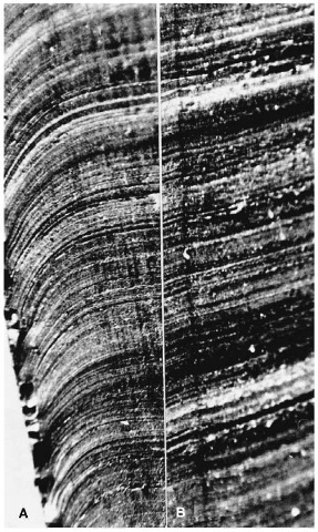
Figure 3 Case study 3. Penknife identified as having stabbed a vehicle tire. (A) Stab cut in tire; (B) test cut. Fine imperfections on the blade (or more specifically the contacting surface) of any implement will determine the number and depth of individual striae, but their spacing relative to each other is governed by the direction of travel. Thus if this penknife blade were scraped across a pat of butter, the same striations would be evident but would bear little resemblance to the mark in the tire.
Collection of Toolmark Evidence
As with almost all forensic science work, toolmark identification relies on sound crime scene investigation practices. Toolmark evidence is more prevalent than is normally accepted, but may often be overlooked because:
• No suspect tool is available for comparison.
• The scene examiner/investigator is not aware of the potential for such evidence, or, if aware, has excluded potential toolmark evidence without proper assessment (i.e. the mark is considered too damaged or too small (see Case study 7), when microscopic examinations can often reveal far more detail than is evident at the scene).
• Investigation of suspect homes, persons or vehicles does not include a search for comparative implements/material.
Rules for collection of toolmark evidence
The following should be adhered to, whether collecting toolmark evidence in situ or by casting.
• General, midrange and close-up photography should be done at a minimum.
• Close-up (macro) photography should incorporate oblique lighting from several directions.
• Trace evidence (paint, metal smears, etc.) may have transferred during the production of the mark. Examiners need to record and prevent both its loss and contamination, on both the mark itself and the suspect implement. The analysis of trace material may provide further associative evidence between the mark and the implement, especially if the comparative results fall short of individualization (see Case study 8).
• All available toolmarks need to be collected. The field technician cannot be certain as to which mark will provide definitive detail;if not collected, valuable information, not able to be confirmed in the laboratory, may be lost. While many scene investigators will collect the striated marks left by a pinch bar, the fulcrum point may also provide valuable detail, particularly when trying to exclude implements in the initial examination stages (see Case study 7.) Both cut ends of a bolt cutter mark, when realigned, will provide a profile of the cutting blades, which often reduces the number of implements requiring detailed examination.)
Case study 7
A chemist shop’s front aluminum door frame had simultaneously been levered some 30 cm above and below the central door lock, just enough to allow the door to be sprung. Minimal damage was done to the door or frame, both of which were still serviceable. While no marks were evident on the edge of the door, the two leverage points were obvious on the thin (2 mm wide) aluminum edge of the door frame. The marks, however, were quite small and showed no class characteristics. Initially not considered to be of any value, the crime scene investigator cast both the marks when advised that two suspects had been questioned and implements had been seized. As the casts were a positive replica of (albeit a very small portion of) the implements used, direct comparison between the casts and the implements themselves was adopted (i.e. no test impressions). The ability to relate both implements and the method employed in their use resulted in both offenders pleading guilty at the time of arraignment (Figs 11-14.)
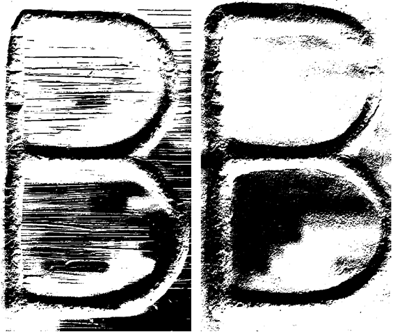
Figure 4 Case study 4. (A) Letter ‘B’ stamped on edge of war medallion; note the grind marks in the background. (B) Letter ‘B’ stamped on copper sheet using one of the jeweller’s stamps. Although some differences can be seen (due either to the substrate on which it is stamped or further damage to the stamp since its original use), an overwhelming number of corresponding defects clearly identify both as having been produced by the same stamp. Standard reflective light microscopy was originally used to satisfy the examiner of the identification, but the use of the electron microscope in this case was an ideal medium for the presentation of the results. The use of this instrument should be assessed as an option whenever very small marks are encountered.
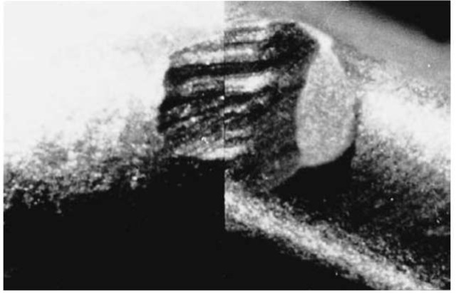
Figure 5 Case study 5. Comparison between a scene mark (left) and that left by tooth number ’5′ on the feeder wheel (right).
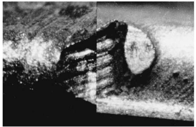
Figure 6 Comparison between scene mark (left) and that left by tooth number T on the feeder wheel (right).
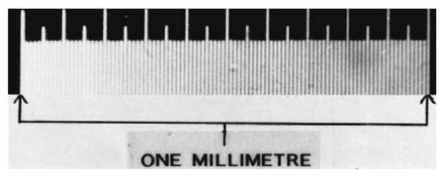
Figure 7 A 1 mm scale included here to give some indication of size. While these marks were only one-tenth the size of the marks in Case study 4 (the letter stamps), electron microscopy was found quite unsuitable for demonstrating the striae comparison results.
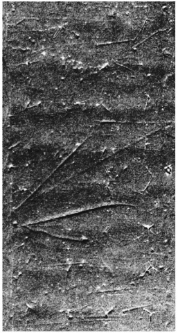
Figure 8 A cast of one small section of the seal produced on a plastic bag.
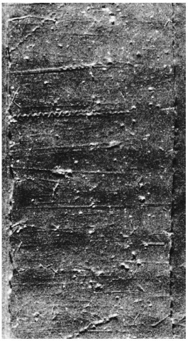
Figure 9 A different section of the cast shown in Fig. 8, further along the heat-sealed plastic bag. The silicon arm, which is pressed down on to the plastic bag during the heat-sealing process, has numerous minute defects whose spatial orientation produces a unique pattern, readily recognizable on any surface (or a cast thereof) that has been sealed by it.
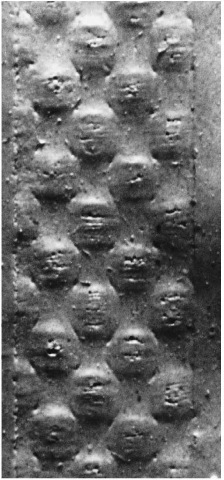
Figure 10 Cast of the sealed surface on the opposing side of the plastic bags sealed with the heat sealer (Figs 8 and 9). The Teflon-coated cloth material which covers the heating element (on the base of such heat sealers) will also be quite different from one sealer to another, with defects developing during use.
In situ collection
The most suitable method for the collection of tool-mark evidence is to collect and preserve the item on which the mark is located. Precautions may need to be taken to prevent deterioration of the mark through damage or oxidation (e.g. a steel chain link may need a thin film of oil to prevent rusting), but the ability to examine the mark itself under laboratory conditions is the ideal. Many items on which the toolmark exists have been damaged in such a way that they will require replacement. As such, most victims have little hesitation in allowing the examiner to collect such evidence. Objects such as doorknobs, chain links, metal sheeting, etc., and even splintered wooden door frames, can be dealt with in this way.
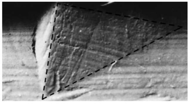
Figure 11 Cast of the lower fulcrum mark left on a 2 mm wide aluminum door-frame edge. The cast has faithfully reproduced the mark as well as some extrusion marks on the aluminum itself.
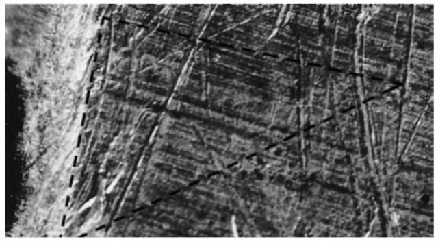
Figure 12 A photograph of a portion of one side of a small screwdriver recovered from one suspect. The detail is located some 12 mm from the actual screwdriver blade and shows both machining and wear features (see Fig. 11).
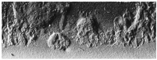
Figure 13 A second cast collected from the scene (Fig. 11) was initially discarded, because of what was perceived to be poor detail. The unusual pattern seen in this second scene cast, however, could be related directly back to a specific section on the second implement, a drop forged crowbar.
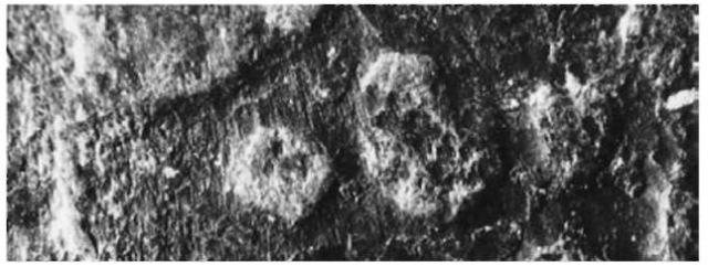
Figure 14 A small section of crowbar identified by a thin smear of aluminum. In this location scaling and other individual features left on the bar during its manufacture were directly comparable, even though a slight dragging of the crowbar across the surface had occurred (see Fig. 13).
Casting
An alternative to in situ collection of toolmark evidence is casting. Often toolmarks exist on items that do not lend themselves to collection. Altered engine numbers cannot be readily examined under the microscope. Damage to some items may be such that they are still serviceable and in situ collection is not an option (see Case study 7).
The most suitable casting materials are those silicon-based media that are simple to mix, easy to apply and to cure with minimum distortion. More importantly, total opacity and the ability to replicate faithfully the finest detail are the two properties that tend to reduce the options available for the collection of toolmark casts. The slightest translucence in the casting medium will reduce the visibility of the surface detail, effectively minimizing the possibilities of demonstrating an identification. Whilst most silicon casting mediums will record the detail, only a few have the opacity suitable for toolmark work.
Good casts should have few or no air bubbles, as even small air pockets can result in loss of valuable microscopic detail. The collector’s detailed notes and photographs, relating the correct position and orientation of the casts, will greatly assist the examiner in determining angles and direction of application, thus simplifying comparison work. This becomes of particular value when the examiner needs to produce test impressions, which require duplication of the direction and angles applicable at the scene.
Examination and Identification
Toolmark identification work requires a simple methodology in which the evidence is analysed, compared and finally evaluated. The techniques applied are not unlike those applied in shoemark identification work, albeit normally at a microscopic level. In almost all cases the use of reflected oblique lighting, a stereo binocular low-magnification (5 – 50 x ) microscope, a low magnification (10 – 50 x ) comparison microscope and an image recording facility (photographic or video) will be the major requirements. Access to a simple workshop to enable the production of test impressions is also recommended.
Scene impressions
Examination of the scene (also referred to as the unknown or the questioned mark) impression is normally carried out first, to determine if it is suitable for comparison purposes. Lighting is quite critical in such examinations, and either the impression or the lighting needs to be angled to produce maximum detail. On some occasions, several lighting angles need to be employed before all the details evident in the mark can be recorded.
Such factors as the nature and quality of the mark, any class characteristics, damage sustained and the existence of individual characteristics are noted prior to any comparative work. At this time the examiner needs to identify those features that have been produced by the implement and are not the product of the substrate on which the mark exists (e.g. wood grain, extrusion or grind marks). Trace evidence also needs to be correctly dealt with before the start of comparative work (i.e. although such trace evidence may not require analysis at this time, it should be noted, recorded, separated and preserved).
Case study 8
Fig. 15 is a mark left (in the plastic coating of an exterior alarm wire), by the side cutting portion of a set of combination pliers. Although comparable to the marks left by the suspect pliers, detail in material such as this is often of poor quality and by itself not sufficient for the total exclusion of other, similar pliers. Caught in the cutting blades of the pliers, however, were copper smears and three different colored particles of plastic, similar to the insulated wiring encased within the alarm wire. The analysis of the plastic and the toolmark comparison work corroborated each other to strengthen the identification (Fig. 15 and Fig. 16).
Suspect implements
The suspect implement(s) are examined next. If the initial scene impressions have been well documented, much elimination work can be achieved at this time. Implements not meeting the dimensions of the scene, having an action not suitable to the production of the scene, etc. can all be excluded. Again, the presence of trace material must be dealt with before the production of test impressions. The position of such trace evidence may also assist the examiner in identifying the specific area of the implement to focus on. (The shape of the chain link can often be seen smeared on the surface of the bolt cutter blades. Without the light smear on the crowbar in Case study 7, the likelihood of locating the impressed detail would have been remote.)
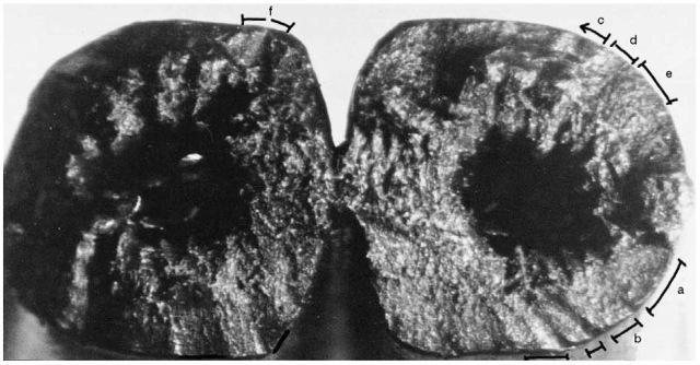
Figure 15 Cross-section of insulated alarm wires believed to have been cut with the side-cutters portion of a pair of pliers. The profile of the cut was quite distinctive and capable of being reproduced by the pliers in question but not by other, similar pliers.
Comparison and test impressions
Comparison between the scene and the implement will normally require the production of test impressions. While some impressed toolmarks (particularly casts) are capable of being directly compared with the implement, the striated toolmark can only be compared with a striated mark produced by the suspect implement. Test impressions also serve the important purpose of demonstrating that the implement is, in fact, capable of producing the mark being investigated.
Test impressions Test impressions should duplicate the conditions under which the original marks were produced, while insuring no damage is inflicted to the surface of the implement. Lead or annealed copper sheeting, aluminum or other soft-metal media are often selected, if the scene impressions were originally produced in metal. There are occasions where the implement will only produce comparable marks in the medium of the original. (This is often the case with marks produced by bolt cutters in hardened steel.) On such occasions, the initial test impressions (in the softer mediums) will provide some guidance before the final test impressions are made in the harder scene material.
Drag or scraping type marks left by crowbars, screwdrivers and the like, are the most difficult type of test impression to duplicate. Marks made by such implements can alter dramatically if the angle of application or the direction of travel across the surface is altered. Changing the angle of application will result in different defects on the implement now being in contact with the marked surface, leaving a different set of striae (Fig. 17). Altering the direction of travel will result in a change in the width of individual striae (Fig. 18). For these reasons striation marks produced by such implements can be difficult to reproduce, and will normally provide the examiner with considerable challenge. Being able to view the striated crowbar or screwdriver mark at the scene will often assist the toolmark examiner in identifying the angle of application and direction of travel. Test impressions made under similar conditions to the scene will maximize the likelihood of producing marks suitable for comparison.
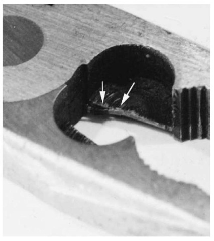
Figure 16 Macrophotograph showing multicolored plastic insulation material caught in cutter blades of suspect pliers.
Sufficient test impressions should be made to demonstrate reproducibility of the features being compared. Most examiners compare test impressions (to demonstrate this reproducibility) before comparison with the scene.
Comparative examinations Comparison between the tests and the scene can now commence. Although the comparison microscope will feature as an important element in this phase, much of the comparison work can, in fact, be performed under low magnification utilizing the stereomicroscope. At this stage the examiner locates features or groups of features that will provide a pattern recognizable in both scene and test. The shape, size and spatial relationship of such features can be quickly observed and noted. In regard to impressed toolmarks, the comparison can often be completed using only the stereomicroscope, as long as lighting conditions remain constant. For striated tool-marks, a careful examination of each mark under similar lighting conditions (particularly direction and angle) will, on most occasions, identify promising areas with similar detail.
The comparison microscope is still the simplest method of comparing striated toolmarks. The lighting conditions on both objectives must be carefully matched before a detailed search for matching contour features is possible. Angles at which the striated detail meets may need slight alteration, but when a match is achieved the similarities of contour are usually striking.

Figure 17 The Effect of alteration in an implement’s angle across a surface. Since varying defects exist on different portions of an implement’s blade, an alteration in the vertical angle as the implement is dragged across the surface will produce a variation in the contour features of the resultant toolmark. Reproduced with permission from Van Dijk (1993). Reprinted from Forensic Science International (1981) Vol 5, pp 18, Maheshwari, Influence of vertical . . . with permission from Elsevier Science.
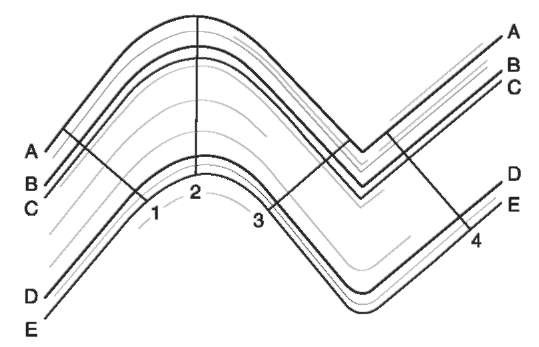
Figure 18 Effect of alteration in direction of an implement across a surface. An alteration in the lateral movement of the implement across the marked surfaces will alter the distance between corresponding striations. If locations 2 and 3 existed as two separate marks, trying to demonstrate a relationship between them would be difficult.
Impressed toolmarks can also be compared using the comparison microscope. Impressed features can be superimposed or compared side by side, confirming size as well spatial relationships.
During any physical comparative process, differences between the scene and test impressions will be inevitable. The use of different materials, damage to the scene or the implement since the mark was first produced and other factors may contribute to such differences. The examiner needs to address any significant differences, especially those that cannot be explained. Unexplained differences will affect the evaluation of any results.
Evaluation of results
As with any physical comparative work, demonstrating a relationship between the scene and the implement under investigation is based on the identification of class and individual characteristics. The existence of comparable class features only will allow the implement to be identified as one of a specific group capable of having made the mark. Whether that group (or class) is limited or extensive will determine whether such findings have any evidentiary value.
The identification of sufficient individual characteristics in both the scene and the implement determines whether individualization, to the exclusion of any other implement, can be reported. The nature of physical comparative analysis is such, however, that there is no minimum number of characteristics required before a ‘positive’ can be reported. Rather the nature and shape of identified characteristics, their relative position to each other, similarity in profile or proportion of matching striae, all influence the examiner. The possibility of another implement having the identified individual features in the corresponding spatial orientation is the basis on which an identification is made. While much work on probability has been carried out, the diversity of implements, the type of marks they may leave, as well as the ever-changing implement surface, have, to date, limited the extent to which statistical data can be developed or applied. As such, possible or probable identifications should not normally be expressed in mathematical terms.
Any evaluation of identified matching characteristics is based on an examiner’s knowledge of the particular implement’s manufacture as well as an appreciation of the physical properties of metals. Research is often required before an examiner is able to provide definitive results as to the origin and cause of comparative features. The research undertaken on specific implements and reported on by various examiners can often be applied to implements whose manufacture incorporates similar processes.
Presentation of results
As with all forensic disciplines, the reporting of tool-mark identification work needs to be unambiguous. The basis of, and any limitations to, the reported findings must be clearly expressed. Reporting in such a manner will insure that the appropriate weight can be placed on the evidence in the context of the case being presented. Two examples of findings are provided:
• The screwdriver (X) is identified as having produced the mark (Y) located on the steel filing cabinet. Based on the matching of striated detail on both Y and a test impression produced by X, this finding excludes any other screwdrivers.
• The screwdriver (X) is capable of having produced the mark (Y) located on the steel filing cabinet. Based on the presence of detail identifying size and shape, but Y lacking sufficient individual characteristics, this finding cannot exclude other flat-bladed implements (i.e. screwdrivers) of the same size and shape.
Having produced a report, it is up to the examiner to provide evidence of the stated results when called upon to do so. Clearly, notes and sketches may be of value but, as can be seen from the case study illustrations, one of the most effective demonstrations of the results achieved is provided through photographs and comparison charts. While such charts may have some limitations, these can readily be explained to any lay person. The adage that ‘a picture speaks a thousand words’ can certainly be applied in physical comparative examinations, and (in the experience of the author) simplifies the reporting process.
Toolmark Identification in the Future
Toolmark identification, it appears, will remain a simple physical comparative discipline for the foreseeable future. The development of improved imaging techniques and the application of computer technology have already provided firearm identification search programmes. Some jurisdictions have applied this technology to develop a database for all striated toolmarks, against which any new case can be searched. These developments will provide more objective data, which the examiner can apply in the evaluation process, but the discipline will remain one of pattern recognition and direct comparison.
Summary
Forming part of a broad range of physical comparison disciplines within forensic science, toolmark identification compares the features present in a scene mark with those present on either the implement itself or a test impression made by it. Relying on sound crime scene investigation techniques for their location and collection, as well as recognition of their value, results of any identification will also be determined by the quality and nature of the mark being investigated.
The working edge or surface of any implement will normally contain features that can be identified as class or individual. Any identification will be based on the existence of such features in the scene mark, and the ability to relate them to the specific implement in question. The application of scientific method, training, experience and research will allow examiners to identify and distinguish between the two types of identifying features. The presence of sufficient individual features will enable examiners to report identity or a relationship between the scene impression and the implement, to the exclusion of any other. The lack of such detail will either exclude the implement altogether or allow it to be placed in a class capable of having produced the mark in question.
Examinations are normally performed utilizing oblique lighting, a low-powered stereomicroscope and a standard low-powered comparison microscope. Lighting and magnification must be duplicated for both scene and known samples. Using direct physical comparison techniques, including comparative measurements, side-by-side comparison and overlays,results of any examination can best be illustrated using comparative micro-and macrophotographs.
