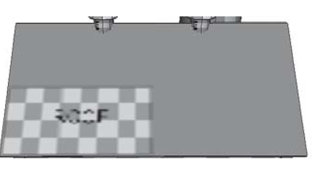
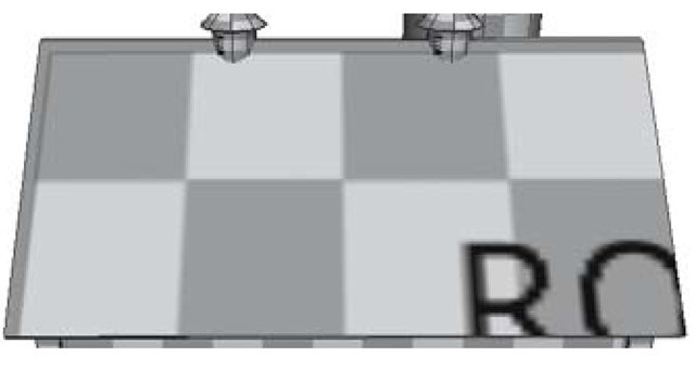
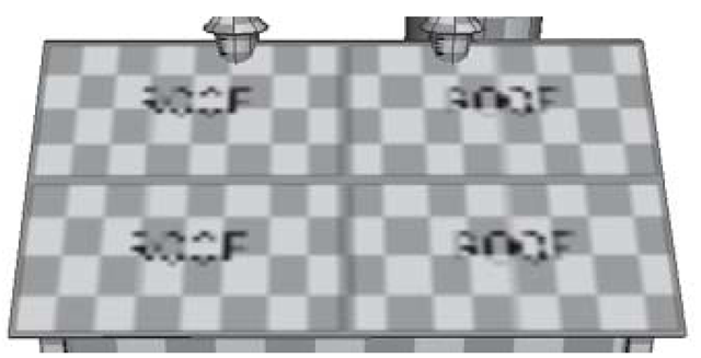
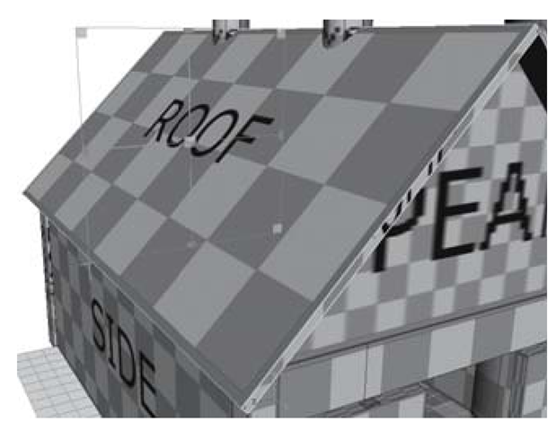
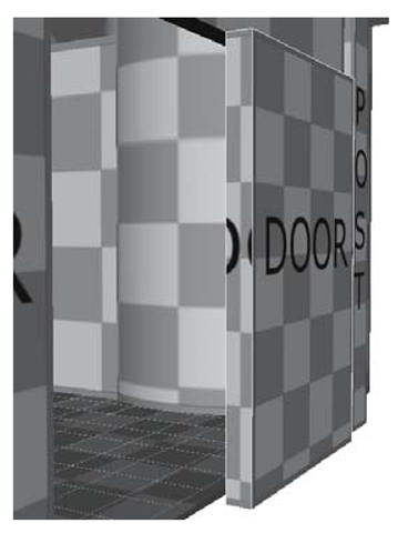
Well, any image file you can create — through painting, scanning, photography, or image creation programs such as Adobe Photoshop — can be used as a texture map on your shader (see Figures 3.60).
Figure 3.60: Texturing an object
By clicking the checker icon next to the Color attribute of a material you will bring up the Create Render Node box. Choose File from the 2D Textures selector. Now, browse to an image file such as a .jpg, .tga, .tif, or .bmp by clicking the folder icon. (The default place to store your images is in the current project’s sourceimages folder.) This image now covers the surface color of the material (see Figure 3.61).
Figure 3.61: File texture in color attribute
Shading Exercise — Barn Textures
1. Set your project to understanding_maya\Chapter03\shading_barn.
2. Open the scene color_barn_begin.ma.
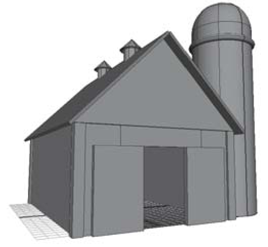
3. You’ll see the barn you created waiting for some texture to be applied (see Figure 3.62).
4. To begin, open the Hypershade and create a new Lambert material. RMB-click on the material, choose Rename from the contextual menu, and rename it lambertRoof. (Hit the Enter key when you are done.)
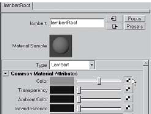
5. Double-click the lambertRoof material sample in the Hypershade in order to open it into the Attribute Editor. Notice the area called Common Material At- tributes; this is where we will change the Color attribute from a simple value to a texture mapped value.
Figure 3.62: Untextured barn
To the right of the Color swatch and slider is the Create Render Node button (the one that looks like a 2 x 2 checker). We are going to connect a file texture to this input. Click on the Create Render Node button. This opens the Create Render Node window. With the Textures tab on top, make sure that the With New Texture Placement box is checkmarked. Now, in the 2D Textures section, be sure that Normal is the selected mode. Finally, click the File button (see Figures 3.63 and 3.64).
So far you’ve specified that the material’s Color attribute is going to be mapped to a File texture. This file texture will be created with a normal, UV-based texture placement utility.
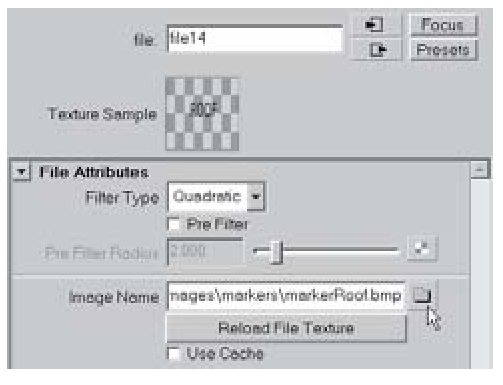
6. The Attribute Editor is now focused on the File node. This is where we can specify which file to use. In the File Attributes section, look for the Image Name attribute. To the right of this is a folder icon. Click the icon to launch a file browser. In the file browser, find the sourceimages/markers directory of the current project. Here you’ll choose the markerRoof.bmp image and click Open (see Figure 3.65).
Figure 3.63: Mapping a file
Figure 3.64: Create file
Figure 3.65: File selection
7. Your lambertRoofmaterial sample in the Hypershade is now colored like the file texture mapped to its Color attribute. MMB-click-drag the material from the Hypershade onto the barnRoof01 and barnRoof02 objects.
8. In the perspective panel, click the 6 key on your keyboard to turn on smooth shading and hardware texturing. You should see the checkerboard pattern with the word “Roof” on it (see Figure 3.66). The other objects already have textures applied. These markers are used to help you align the mapping of textures to your objects. Once the mapping is correct, you can swap the markers for your final textures.
Figure 3.66: Textured barn
There are two things working together to make your texture map appear correctly on an object. One is the place2dTexture placement utility connected to the file. The other is the UV mapping of the object itself. Let’s take a look at these things and how they work together.
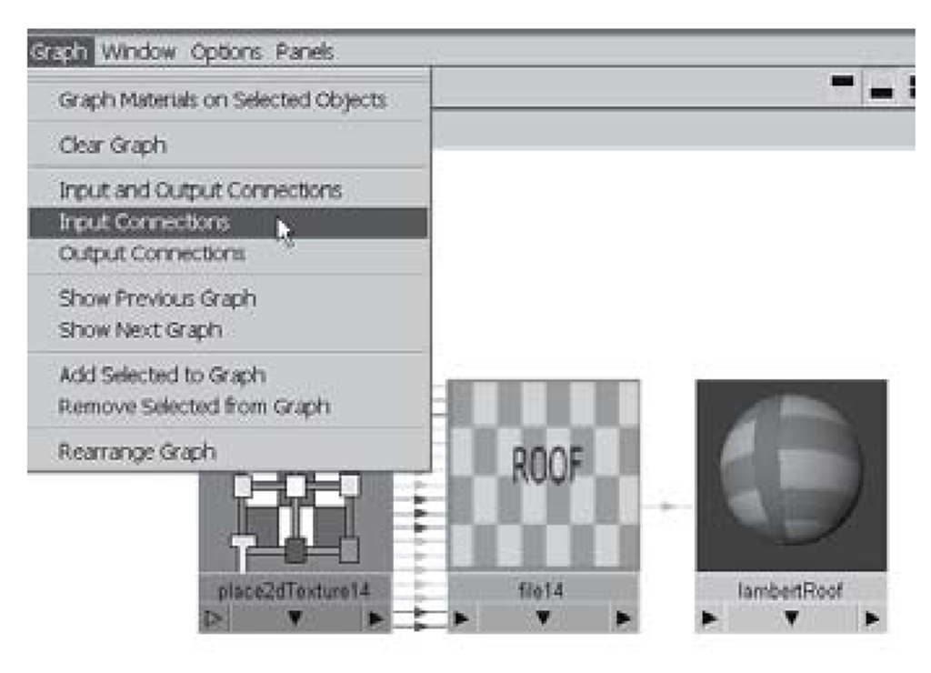
9. In the Hypershade, select the lambertRoof material (a yellow outline surrounds the selected material). In the Hypershade menu, click Graph > Input Connections. You’ll now see in the Work Area of the Hypershade three connected nodes (see Figure 3.67). The place2dTexture14 utility node, the file14 node (this contains a link to the bitmapped graphic file named markerRoof.bmp), and finally the lambertRoof material node. Double-click the place2dTexture14 node to open it in the Attribute Editor.
10. The place2dTexture14 node determines how the file texture is displayed within the UV texture space of the object. The roof objects were originally created from polygon cube primitives that had automatically assigned texture coordinates. Each face of those cubes was set to fill the entire UV texture space. So the Coverage setting of 1.000 (U) and 1.000 (V) that you see in the Attribute Editor right now places one iteration of the file texture inside each face, from corner to corner.
Figure 3.67: Graph input connections
a. Try changing the Coverage to 0.5 (U) and 0.5 (V) and see what happens. Only one quarter of the available UV space is covered by the file texture (see Figure 3.68).
b. Now, try a Coverage of 2 (U) and 2 (V). The UV space of each face is only able to display one quarter of the total file texture (see Figure 3.69). When done, reset the Coverage to 1 (U) and 1 (V).
Figure 3.68: Coverage of 0.5, 0.5
What this means, is that based on the UV mapping coordinates of a given surface, the place2dTexture utility can be used to display more or less of a texture within that space. For another example, try changing the Repeat UV settings to 2, 2. Again, the UV texture space of each surface remains the same, but the number of texture iterations within that space has changed (see Figure 3.70).
11. Reset the Repeat UV settings to 1, 1.
Figure 3.69: Coverage of 2, 2
12. One look at the barnRoof02 object and you can tell that there’s a texture-mapping problem. The word “Roof” is upside down. You may want to try fixing this problem by altering some settings in the place2dTexture1 node. Take a look at the Rotate UV attribute. If you set the slider to a value of 180° you’ll see the entire texture rotate to the correct orientation. There is a problem, however; take a look at the barnRoof01 object. Its texture is now upside down! Reset the Rotate UV attribute to 0.
Figure 3.70: Repeat of 2, 2
13. So what’s going on? How can you fix one side of the roof without ruining the other? The answer lies in the UV mapping of the individual objects. You see, the lambertRoof material (along with its connected file1 texture and place2dTexture1 utility) is assigned to both objects. Any changes to the material will be seen on both objects. What can be changed is the explicit UV mapping of the individual objects.
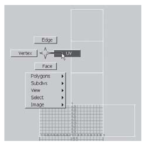
14. Select the barnRoof02 object in the Perspective panel. Then click Windows > UV Texture Editor . The UV T exture Editor shows you the UV coordinates of your model in a flattened view. Click Image > Display Image in order to turn off the markerRoof.bmp image (which will drive you mad if you stare at it for too long). What you’ll see is the unwrapped cube sitting on the UV texture space (see Figure 3.71). (If you don’t see anything at first, dolly out or press the a key on your keyboard to frame the unwrapped cube.)
15.We want to rotate the barnRoof02 object’s UVs 180° in order to flip the texture. RMB-
click anywhere inside the UV Texture Editor and choose UV from the marking menu. Now, marquee-select across the entire wireframe to pick all of the UVs. They’ll highlight to a green color when selected.
16.With the UVs selected, click in the UV Texture Editor’s menu on Polygons > Rotate UVs options.
Change the Rotation Angle setting to 180°. Click the Rotate button. The texture now looks correct on the barnRoof02 object (see Figure 3.72).
17. You can now close the UV Texture Editor.
Figure 3.71: Picking UVs
18. Use this same technique to correct the barnWall02 object’s UV coordinates.
19. On many workstations, once you alter the settings of the place2dTexture node, your hardware texturing will get very blurry. To correct this, select the material node (lambertPeak in this case) and look for the Hardware Texturing settings in the Attribute Editor. Change the Texture quality attribute from Default to High or Highest. Only change this setting when making critical adjustments; you may experience slow frame rates depending on your graphics card’s memory, drivers, and chipset if too many materials are displaying high-quality textures. Note: These settings do not alter the texture quality of software rendering. Only real-time, OpenGL-based rendering is affected.
Figure 3.72: Before and after rotating UVs
20.The peaks of the barn are in need of some texture rotation. Unlike the roof objects, this can be fixed in the texture placement utility. Remember, changes in the texture placement utility will be seen on all objects that share a material assignment. In this case, such a change is a good thing, since it speeds up your work. In the Hypershade, select the lambertPeak material. Now, select the place2dTexture5 tab in the Attribute Editor. Set the value for RotateUV to 90°.
21. This UV rotation has taken care of the texture rotation on the barnWall07 and barnWall08 objects, but now it’s evident that the texture is misaligned and stretched. We can fix these problems by changing the translation and repetition values of the texture placement node. Try changing the Translate Frame settings and the RepeatUV settings until you see the red border edges and the checkers are square. (I settled on Translate Frame = 0.260, – 0.080 and RepeatUV = 1.350, 1.190 as seen in Figure 3.73).
22.Another object that can be corrected through the place 2dTexture node is the siloWalls object. Pick the lambertSilo material in the Hypershade. In the Attribute Editor, click on the input connections button next to the Color slot. Choose the place2dTexture8 tab at the top of the Attribute Editor. Change the RotateUV value to 90°.
Figure 3.73: Original; RotateUV = 90°; Translate Frame = 0.26, -0.08 and RepeatUV = 1.35, 1.19
23. This orients the texture correctly, but it would be nice to have the red border seam at the back of the object, with the word “Silo” on the front. To change this, you can alter the Offset value of the place2dTexture8 node. The second field (V) corresponds to this direction in the texture space of the cylinder. Set the Offset values to 0 (U) and 0.5 (V). Now the texture faces the front of the object.
24. Once again, the texture may have become blurry. If you need to sharpen it for placement purposes, increase the Hardware Texturing > Texture quality setting. This is found in the lambertSilo material node.
25. The dome on top of the silo can be fixed in a similar way. Select the lambertDome node, open the place2dTexture9 node in the Attribute Editor, and set the RotateUV attribute to 90°. Set the Offset (V) value to 0.5.
26.The siloRing object is also going to need a texture placement node adjustment. Again, the RotateUV must be set to 90° to correct the orientation. The Offset (V) should be set to 0.5 to place the word “Ring” on the front of the silo ring. Since the texture is currently wrapped all the way around the object, half of it is hidden. On the U direction of the object, we want to repeat the texture twice — once for the visible outer portion of the object, and once for the hidden inner section. Set the RepeatUV setting to 2 (U) and 1 (V). Notice how this makes the red border edge of the placement marker visible on all edges of the object.
27. For the barnVent objects and the barnHood objects protruding from the barn’s roof, the same technique you used on the siloWalls will work. Choose the lambertVent material and change its place2dTexture11 node’s settings to RotateUV = 90° and Offset = 0 (U) and 0.5 (V). Use these same settings on the lambertHood material’s place2dTexture12 node (see Figure 3.74).
28. The barnFloor object will be easy to fix. Change the lambertFloor material’s texture placement node to a RotateUV value of 270°.
Figure 3.74: Fixing the vent and hood
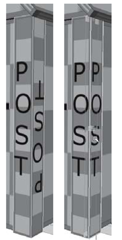
The barnPost03 and barnPost04 objects have some problems with UV orientation on their outside faces. In this case, we’ll need to apply a completely new set of mapping coordinates to those individual faces. The posts were created originally from polygon cube primitives, with their default texture settings. In this mode (named Normalize the Whole Object) the faces of the cube have shared UV texture points. This is similar to having neighboring polygons share vertices. If you move a vertex on a cube you affect all connected faces. The same is true of moving UVs when they are shared. What this means is that you cannot alter the UVs of the one problem face without causing new problems on the connected face. What we want is to normalize the UV textures onto individual faces.
29. Select the barnPost03 object. In component mode (F8), select the face with the upside-down “Post” writing. In the Modeling menu set, click on Edit Polygons > Texture > Planar Mapping options. Here you are able to choose the size, po- sitioning, and direction of the new set of UV coordinates. Click Edit > Reset Settings to choose the defaults. Change the Image Scale value to -1 (U) and 1 (V). (This will keep the coordinates from going on backward.)
Figure 3.75: Fixing posts
30. Click the Project button. You’ll see a correctly oriented texture marker on the side of the post, as in Figure 3.75. (You’ll want to return to object mode after applying projections; Maya automatically selects the object’s faces after you create a projection.)
31. Repeat this process for the barnPost04 object.
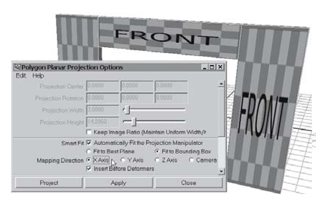
32. We’ll use a similar technique to unify the three objects that comprise the front wall of the barn. When multiple faces or multiple objects are selected, the Planar Mapping command will fit the projection around the entire selection area. First, select the barnWall04, barnWall05, and barnWall06 objects. Then click on Edit Polygons > Texture > Planar Mapping options. Click Edit > Reset Settings to reset to the defaults. Looking at the scene in the perspective panel, you can see that the front walls of the barn are facing down the X-axis. So in order to map the projection properly, click on the Mapping Direction setting’s X axis radio button. Then click the Project button (see Figures 3.76 and 3.77).
Now the three front wall objects have consistent mapping coordinates. This means that you won’t see any seams between the objects, and they will display textures with the same density and aspect ratio. This density of texture on an object’s surface is known as texel density. When the objects in a scene have uniform texel density they appear to belong together. When the texel densities are mismatched, your scene will look more like a bunch of individually constructed parts, rather than a collective whole.
Figure 3.76: Planar projection options
Figure 3.77: Unified texture
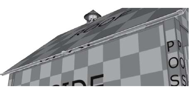
The same corrections should be made for the small faces of the roof and door objects. (The walls have this problem too, but those faces are hidden, so you don’t necessarily need to fix them.) In these cases, we’ll want to interactively translate, rotate, and scale the planar projection manipulators to get a tight fit (see Figures 3.78 – 3.81).
33. Select the barnRoof01 object’s top and bottom faces. (Note: These faces are the ones with the stretched textures on them, not the large faces we mapped at the beginning of the exercise.) Click on Edit Polygons > Texture > Planar Mapping options. Click Edit > Reset Settings and change the Mapping Direction to Y axis. As with the posts, we need a different aspect ratio than the default. Try an Image Scale setting of 1 (U) and 0.6 (V). Then click the Project button.
Figure 3.78: Projecting the bottom and top faces
34. Repeat the above step for the barnRoof02 object.
35.In component mode, select the two diagonal end faces on the barnRoof01 object. Then click Edit Polygons > Texture > Planar Mapping options. Reset the settings to default, then choose Mapping Direction = X Axis, and Image Scale = 1 (U) and 0.6 (V). Then press the Project button.
36.In the perspective panel, look at the polyPlanarProj manipulator. It is a multifunction manipulator used for translating and scaling UV texture coordinates. The red and green lines control translation. The red and green boxes control scale. Try these handles out now, and when you’re done, undo the changes.
Figure 3.79: Selecting end faces
Figure 3.80: Projecting the end faces
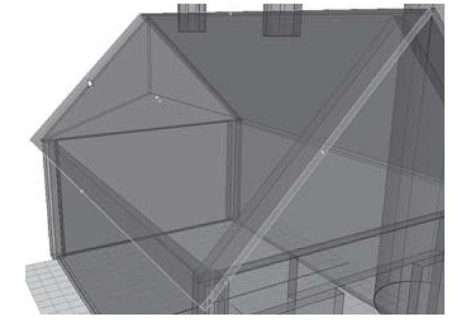
By clicking the red, cross-shaped handle in the corner, you switch the manipulator’s mode to that of a multiple transform tool. This offers the same control as the default mode, plus the ability to rotate the projection. Click the light blue circle in order to invoke the familiar rotate manipulator. You will use some of these tools to rotate the texture projection on the diagonal end faces of the roof objects.
37. The texture mapping coordinates have been applied at the wrong angle for the selected faces. To correct this, click on the red cross handle in the corner of the projection manipulator. This switches the mode of the manipulator. Click once on the light blue circle to bring up the rotation rings. Drag the blue rotation ring to 45°. (In the Channel Box this reads as the Rotate Y channel.)
38. Now, drag the red scale box to a Projection Width of 13.65. This type of interactive projection placement is very helpful when you’re texturing your surfaces.
39. Repeat the previous three steps for the barnRoof02 object.
40. The door objects’ top faces should be fixed next. Select the barnDoor_left object. In component mode, pick the top and bottom faces. Assign a planar projection from the Y Axis, with an Image Rotation of 90°, and an Image Scale of 0.1 (U) and 1 (V) (see Figure 3.82).
41. Repeat the previous step for the barnDoor_right object.
Figure 3.81: Rotating and scaling the projection manipulator
Figure 3.82: Top projection for the door
42. The final correction will be the side faces of the door objects. Pick the barnDoor_left object’s two side faces. Assign a planar projection from the Z Axis, with an Image Scale of 0.1 (U) and 1 (V) (see Figure 3.83).
43. Repeat the previous step for the barnDoor_left object. Be sure to save your scene.
Whew, we made it! Now you can assign any file texture in place of the texture markers and know that your placement, rotation, and texel densities will be correct (see Figure 3.84). One easy way to do this is to use the marker image files as a background template when painting in Photoshop or any other image-processing application.
Figure 3.83: Door side fixed
Figure 3.84: Final barn with replaced textures
