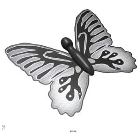
Look at most objects in the real world and you’ll find that they have not just color, ^—I JA texture, and shininess but a whole host of other attributes that make them unique.
The surface of a piece of sandpaper, for example, has a “bumpiness” that is caused by many tiny bits of sand that are adhered to the paper. In Maya, you can map a file texture or simple noise texture to the bump map slot of a material to mimic this effect. A bump map will cause the light that hits the object’s surface to play off it as if there were actual positive and negative depths.
Bump Maps
Without adding geometry to the surface of a sphere, bump maps increase the perceived detail (see Figure 4.50). With the exception of very smooth surfaces such as glass and polished stone, almost all materials should incorporate some amount of bump mapping.
Figure 4.50: Identical geometry before and after bump mapping with this pattern
Transparency
The transparency of a material determines – you guessed it – how see-through it is. You may simply change the Transparency attribute with the slider. For more specific, localized, or complex transparency it’s possible to map a texture to the transparency attribute.
A black and white polkadot pattern placed into the transparency slot, for example, will cause an object to have alternating opaque (where the map is black) and transparent (where the map is white) areas when rendered (see Figure 4.51).
Figure 4.51: Identical geometry before and after transparency mapping with this pattern
Shading Exercise — Butterfly
1. Set your project to understanding_maya\Chapter04\shading_butterfly.
2. Create a new scene.
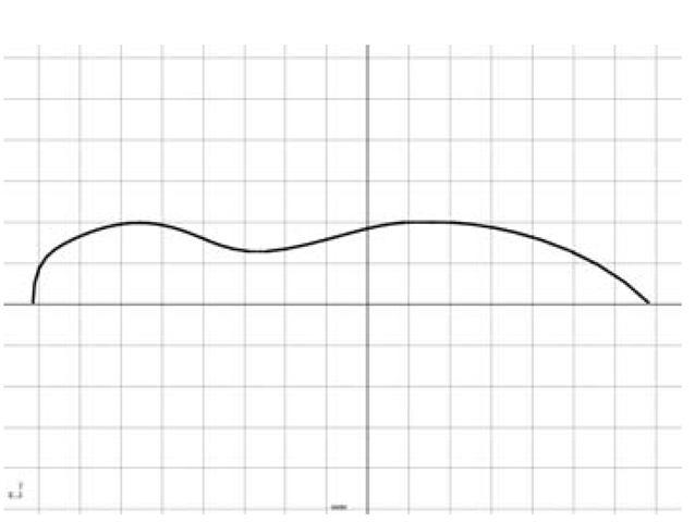
3. In the side view, create a curve in the half-profile shape of a butterfly’s body, being careful to snap the first and last points to the thick grid line at the Z-axis origin by turning on Grid Snapping (see Figure 4.52).
4. With the curve selected in Object Mode, use the Revolve command with the axis set to Z to create the surface.
5. Name the object butterflyBody.
6. In CV selection mode, reshape the points of the surface to create a better shape (see Figure 4.53).
7. Now we’ll create some simple wings. Click on Create > Polygon Primitives > Plane options. Set the number of Subdivisions Along Width and Subdivisions Along Height to 1, and click Create.
Figure 4.52: Revolve curve
Figure 4.53: Butterfly body
8. Name the plane leftwing.
9. In the top view panel, move and scale leftWing into position, about 10 on TranslateX, 20 on ScaleX, and 30 on ScaleZ.
10. When you’re developing the look of your scene, it can be helpful to arrange the panels with a Perspective and Hypershade split, as well as the Attribute Editor docked on the right side of the workspace. Once you have this set up, create a new phong material, and name it phongWing.
11. AssignphongWing to the leftWing object by MMB-drag-dropping it. In the perspective panel, smooth shade the scene and turn on hardware texturing by pressing 5 and then 6 on your keyboard (see Figure 4.54).
Figure 4.54: Butterfly wing
Figure 4.55: Color and transparency applied
12.Next we’ll map some of the phongWing material’s attributes with file textures. In the Attribute Editor, click on the Create Render Node button (the little checker icon) to the right of the Color attribute. When the Create Render Node window pops up, choose the Textures tab, check With New Texture Placement on, choose Normal from the 2D Textures turn-down menu, and then click on the File icon. In the file field, rename this node fileWmgColor.
13.In the Attribute Editor, click the folder icon next to the Image Name field. From the Open window, choose the bfly_color.tga image, then click the Open button. (The 32-bit Targa file contains 24 bits of color information and an 8-bit alpha channel, which is used to specify areas of transparency. Maya will automatically connect this file node to both the color and transparency attributes of the material.)
14.To map the texture correctly on the leftWing object, choose the Modeling menu set, and select the leftWing object. Then click Edit Polygons > Texture > Planar Mapping options. Reset the settings, then choose Y Axis in the Mapping Direction setting. Then click the Project button.
15.The leftWing is now mapped with the color and transparency texture. It’s currently upside down, so we’ll fix that in the Attribute Editor. ThepolyPlanarProjl tab of the leftWing object should be selected. Under the Projection Attributes turn-down menu, set the Rotate attribute to 90, 0, 0.
16.Select the phongWing material in the Materials tab of the Hypershade. Then, click Graph > Input Connections. This expands the shading network graph in the Work Area tab, revealing the connections between the fileWmgColor node and the phongWing node’s color and transparency attributes.
17. Hover the cursor over the top connection between the file and material nodes. You’ll see a bit of pop-up text appear to indicate which attributes are connected. In this case it says that the fileWingColor.outColor attribute is connected to the phongWing.color attribute.
18. This time, hover the cursor over the bottom connection between the file and material nodes. This indicates that the fileWingColor.outTransparency connects to thephongWmg.transparency attribute (see Figure 4.55).
Figure 4.56: Improper specular map
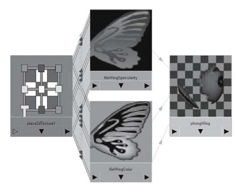
Figure 4.57: Shading network
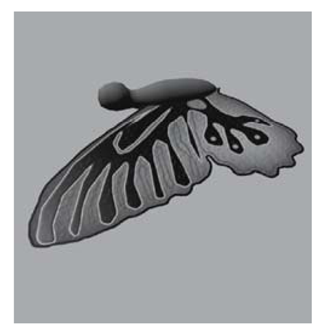
Figure 4.58: Corrected specularity
19. Render a single frame of your scene. You may notice that from certain angles, the effect of the transparency is ruined due to the specularity of the Phong material, as in Figure 4.56. We’ll use a specular map texture to specify shiny parts of the wing.
20.Select the phongWing material in the Hypershade. In the Attribute Editor, click on the Create Render Node button next to the Specular Color attribute. Uncheck With New Texture Placement, and choose File texture. For the Image Name attribute, browse to the bfly_specularity.bmp file. Rename this node fileWingSpecularity.
21.The fileWingSpecularity node needs to use the same 2d placement utility as the color file. This can be done in the Hypergraph by MMB-drag-dropping the place2dTexturel node onto the fileWingSpecularity node and choosing the Default option (see Figure 4.57).
22.Now re-render the frame. The shiny area has been corrected, as in Figure 4.58.
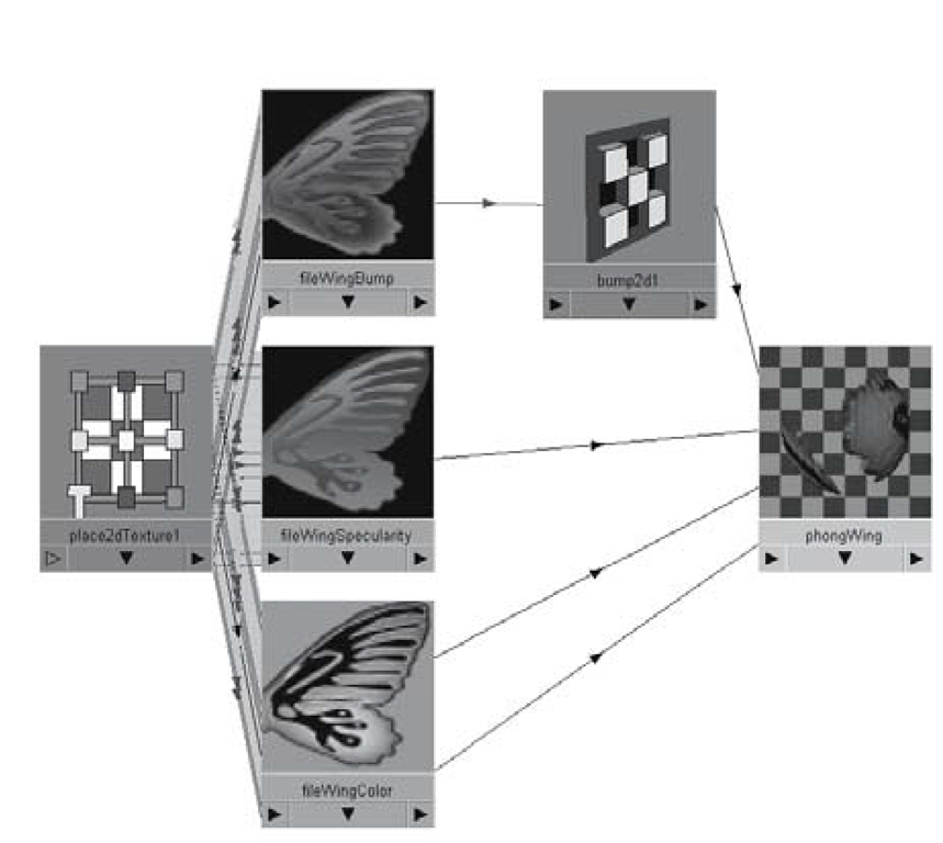
23. The last file you’ll map is for the bumpiness of the material. Select the phongWing material. In the Attribute Editor you will click the Create Render Node button to the right of the Bump Mapping attribute. Again, choose a File texture. This will create two things: a Bump 2d utility, and a File texture. Rename the bump2d1 node bump2dWing. Rename the file texture fileWingBump.
24.Select the fileWingBump node. In the Attribute Editor, browse to the bfly_bump.bmp file. As before, connect the shared place2dTexturel node to the fileWingBump node (see Figure 4.59).
Figure 4.59: Finished shading network
Figure 4.60: Duplicated wing
25. Re-render the scene to see the change. If you want less extreme bumpiness, lower the Bump Depth value of the bump2dWing node to something more moderate, like 0.3.
26. Now you can duplicate the leftWing object with a ScaleX value of -1, to mirror it. Move it into position on the other side of the body (see Figure 4.60).
27. Save your scene as shading_butterfly_end.ma.


