The type of light we see in the real world is a very complex entity to re-create on the (sj computer. It’s the actual energy of light bouncing off surfaces, casting colored bounce light and soft shadows, that we try to emulate when placing light sources in Maya.
The spot, point, and direct lights we’ve used so far are fairly simple, largely unrealistic types of light when photorealism is the goal.
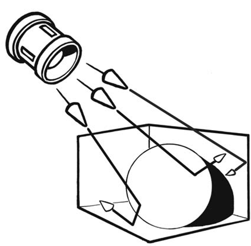
Some rendering engines, such as mental ray, use a method of indirect light calculation called global illumination. Global illumination approximates the actual energy of light and its ability to bounce from one surface to the next (see Figure 4.61). In a traditional live-action lighting scheme, many bounce cards are set up to increase the amount of reflected light. Radiosity renderers can use such bounced light as well. However, radiosity can be a very slow, processorintensive way to achieve realistic lighting.
A way to fake such bounced light in Maya’s software renderer is to supplement your lighting setup with Area lights. Area lights are two-dimensional cards that emit light from multiple points on their surface. You can place them in your scene much as you would a bounce card in a live-action film shoot. They will cast light from their surface and can be resized to tune the lighting. Changing their color will help achieve the radiosity look.
Figure 4.61: Bounced light
Lighting Exercise — Cornell Box Area Lights
1. Create a NURBS cube by clicking Create > NURBS Primitives > Cube. NURBS cubes are actually a group containing six planes to define the sides. Since these planes are separate objects, we can easily color them independently of each other. However, we need to be careful to select the highest node (nurbsCubel) before moving, rotating, or scaling the cube, or else it will fall apart.
2. Scale and translate the nurbsCubel node to create a room for our lighting test. A scale value of 8 on all three axes will work. Translate 4 units on the Y-axis to set the bottom of the cube on the grid.
3. Delete the face of the cube named frontnurbsCubel. Removing this wall allows us to peer inside the room.
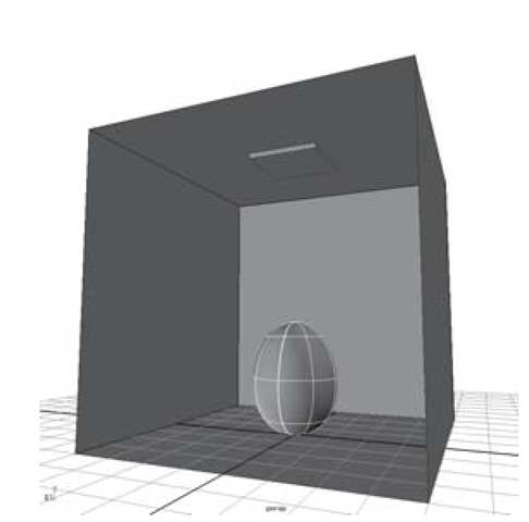
Figure 4.62: Room and egg
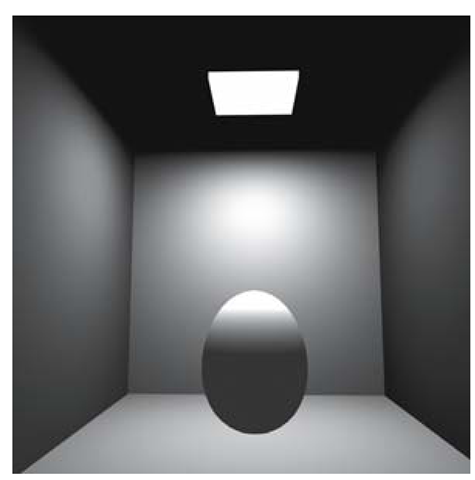
Figure 4.63: Rendered top area light
4. To suggest a light source for the room, create a polygon cube primitive, rename it lightbox, and place it just below the ceiling. Translate it to 0, 7.9, 0 and scale it to 2, 0.15, 2.
5. Create an egg to place inside the room. You can start with a NURBS sphere and then adjust the CVs to form the egg shape. Rename the object egg (see Figure 4.62).
6. Open the Hypershade by clicking Window > Rendering Editors > Hypershade… Create four Lambert materials. Color one red, one blue, one off-white, and one white. Assign the red material to the left wall, the blue one to the right, the off-white one to the floor, ceiling, and back wall, and the white one to the egg.
7. Create a Lambert material for the light fixture. Color this one white, and set its Incandescence value to white. This will add to the illusion that it is emitting light.
8. Next, to begin lighting, click Create > Lights > Area Light. Move the area light to the top of the room (7.9 on the Y-axis) and rotate it -90° on the X-axis so it points down. Hit the 7 key on your keyboard to view interactive hardware lighting.
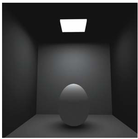
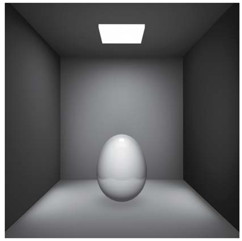
9. Render the current frame and notice the nice throw pattern of light on the walls (see Figure 4.63). There are dark corners and bright centers to the walls. Area lights emit more or less light, depending on their size. Scale the light up to 1.25 on all three axes and then re-render the frame. Notice how the lighting has increased. See Figure 4.63.
10. In the Attribute Editor, lower the area light’s intensity to 0.35, then render the frame. The lighting on the egg is a bit more subtle this way, but it hits the walls more evenly.
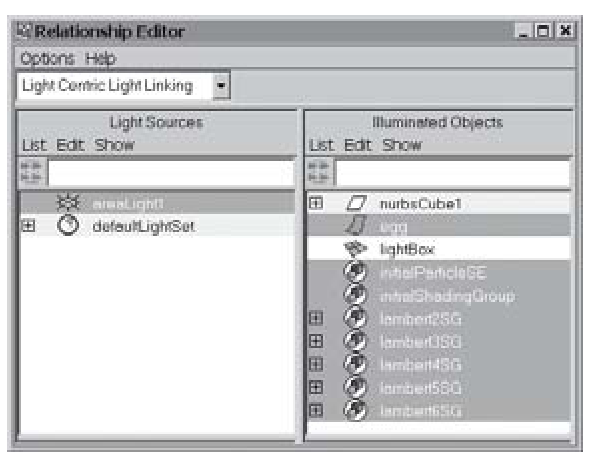
Figure 4.64: Light linking
Figure 4.65: Softened shadows
11. Turn on the Use Depth Map Shadow checkbox for the areaLightl. Render and you’ll notice a problem — the lightBox object is casting a shadow and obscuring most of the light. In order to remedy this problem, open the Window > Relationship Editors > Light Linking > Object-Centric… In this window, the object that you select on the left can be linked or unlinked from the scene lights as in Figure 4.64. Click the lightBox entry in the Illuminated Objects list. Notice that areaLight1 is highlighted in the Light Sources list, indicating a connection. To break the connection, click on areaLightl in the list. Render the frame and you’ll see that the problem has been fixed.
12. Now the egg’s shadow looks a bit sharp. In the Attribute Editor, change the Dmap Resolution to 64, and set the Dmap Filter Size to 5. Render a frame and you’ll see that this softens the shadows as in Figure 4.65.
13. Create another area light for the left wall. This one will simulate a red light being reflected off the wall. Leave the rotation values at 0,0,0, and move it to 0, 2.5, 4. Again, try a low intensity between 0.05 and 0.1. Set the light’s color attribute to an HSV value of 360, 0.3, 1. Render the scene to see the result.
14. You can duplicate the left wall light to create the blue light for the right wall. Move the new light to 0, 2.5, -4 and rotate it 180° on the X-axis. Change the light’s color attribute to HSV 240, 0.3, 1 in order to add a bluish cast.
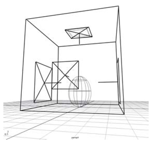
15. We need to add one more area light to the scene to cast light from the front (see Figure 4.66). Translate the new light to 3.3, 2, 0 and rotate it 90° on the Y-axis. Set the intensity to 0.2.
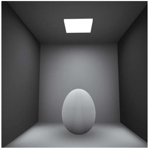
16. Render the scene. You should see an image similar to Figure 4.67.
Figure 4.66: Light positions
Figure 4.67: Fully lit egg
Raytracing
Raytracing is an accurate method of calculating the reflections light rays make as they bounce around your scene. The path of a given light ray is “traced” by Maya’s renderer, resulting in precise interpretations of your light placements, shadow and material reflections, transparency, and refraction.
The first step in using raytracing is to turn on the Raytracing option in the Render Globals. Next you must specify where you want to spend the extra rendering time (raytracing is not fast) in your scene. By using raytraced shadows in your lights and turning up the reflectivity in a shader you’ll begin to see realistic interactions of light and surfaces.
Lighting Exercise — Shiny Egg Raytrace
1. Set your project to understanding_maya\Chapter04\lighting_raytrace.
2. Open the scene lighting_raytrace_box_begin.ma.
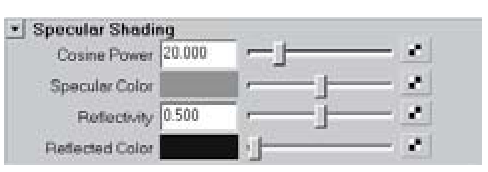
3. Select the egg object and open the Attribute Editor. Pick the lambertegg tab, and then change the Type attribute from Lambert to Phong. Notice one of the new attributes available in the Specular Shading area is Reflectivity (see Figure 4.68). Once raytracing is enabled, this value will determine how reflective the surface is.
4. Open the Render Globals by clicking the third clapboard icon on the Status Line. Set the Resolution to the 1k Square preset. Also, increase the Anti-aliasing Quality to Intermediate.
5. In the Raytracing Quality section of the Render Globals, click the checkbox to turn on Raytracing. Then, set the Reflections to a value of 3, and the Refractions and Shadows to 0.
6. Render the frame. You’ll see the room reflected off the egg’s surface.
7. Now, try increasing the Reflectivity value of the egg’s Phong material to a value of 0.75. When you render again, the egg will be more reflective (see Figure 4.69).
Figure 4.68: Reflectivity attributes
Figure 4.69: Raytraced render
You’ll notice that the egg is reflecting an empty black area where the front wall of the room is missing. Rather than build more geometry to correct this problem, you can use a file texture. The Reflected Color attribute of the Phong material will be used on any part of the egg that isn’t reflecting true scene geometry. This is a great way to suggest a complex environment.
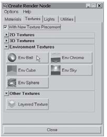
8. Select thephongl material in the Hypershade. In the Attribute Editor, click the Create Render node button next to the Reflected Color attribute. Choose the Env Ball texture from the Environment Textures dropdown list, making sure that With New Texture Placement is turned on (see Figure 4.70).
Figure 4.70: Env ball texture
The environment ball lets you map a file texture to the inside of an invisible, infinitely large sphere that surrounds your scene. This image is usually created by photographing a chrome ball (such as a large Christmas tree ornament) in an environment you want to capture. This distorted image is then un-distorted and reflected off your 3D objects.
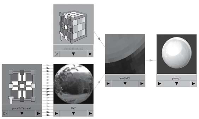
9. You can graph the shader network you are working on, by selecting the phongl material in the Hypershade, and clicking Graph > Input Connections. Select the envBall3 node.
Figure 4.71: Env ball mapped to the reflected color attribute
10. In the Attribute Editor, click the Create Render node button next to the Image attribute. Choose File from the 2D Textures dropdown list.
11. Click the Image Name folder, and browse to the sp_bfrm.bmp image (see Figure 4.71).
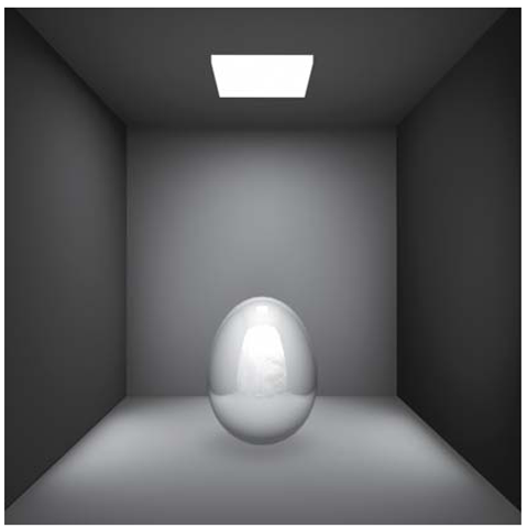
12. Render the frame. This time you see an outdoor reflection in the egg, along with the true scene reflections (see Figure 4.72).
Figure 4.72: Outdoor reflection
