ABSTARCT
This research developed a reliable intelligent non-destructive evaluation (NDE) expert system for Carbon Fiber Reinforced Panels (CFRP) panels based on infrared thermography testing (IRT) and post processing by means of fuzzy expert system technique. Data features and NDE expert knowledge are seamlessly combined in the intelligent system to provide the best possible diagnosis of the potential defects and problems. As a result, this research help ensure CFRP panels’ integrity and reliability. Specimens with simulated defects were evaluated to demonstrate the usefulness of the intelligent IRT NDE expert system in NDE inspection. The testing data pattern corresponding to feature and quantification of defects were found. This fuzzy expert system not only eliminates human errors in defect detection but also functions as NDE experts. In addition, fuzzy expert system improves the defect detection by incorporating fuzzy expert rules to remove noises and to measure defect size more accurately. In the future, the expert system model could be continuously updated and modified to quantify the size and distribution of defects. The system developed here can be adapted and applied to build an intelligent NDE expert system for better quality control as well as automatic defect and porosity detection in CFRP production process.
Introduction
Carbon Fiber Reinforced Plastics (CFRP) are becoming more popular every day. They are currently being used in a variety of applications in aerospace and researchers are looking into using it in building structures due to their high strength to weight ratio [1]. Currently the manufacturing process to make CFRP is very complex so it is crucial to make sure that the final product is flawless. Infrared Thermography (IRT) is an ideal non-destructive evaluation method for looking at CFRP because it is non-invasive, non-contacting and can analyze large areas at one time [2-8]. However, being able to find these defects is based on the operator’s experience, and improper testing can result in defects not being found. Therefore, implementing and operating intelligent IRT NDE expert system for CFRP would be reliable, economical, and easy to the industry. In summary, the ability to evaluate CFRP by IRT NDE methods is important to many industries which produce and use CFRP. Hence, the goal of this study is to develop intelligent NDE expert systems which provide expert knowledge and experiences to help the NDE technicians during inspection. Although IRT NDE techniques have been tested and proven for CFRP, an intelligent IRT NDE system for CFRP has not been demonstrated. Therefore, this research contributed to advancing intelligent IRT NDE system technologies in CFRP.
IRT Method
The experiments were conducted at Southern Illinois University Carbondale’s (SIUC) Intelligent Measurements and Evaluation Laboratory (IMEL). Experiments were conducted using four 500 Watt halogen linear tubes as the heat source. The equipment used in these experiments was the SIUC thermography system. The infrared camera that was used in these experiments to record the thermal images was a MikroSpecRT thermal imaging camera with a resolution of 0.06°C at 30°C, a measurement accuracy of + 2°C of reading, and 320 x 240 dpi. The error of IR camera rounds the 0.06°C up to 1°C, since there is noise associated with the camera and the material properties such as thermal diffusivity and emissivity. The CFRP is an orthotropic material and the thermal diffusivity changes throughout the sample which can cause different temperature readings on the surface. To make sure that and actual defect is being detected and not just noise due to either the camera or the material, the analyzed thermal changes should not be smaller than 0.2°C. The thermal image infrared camera unit incorporated a black and white or (grayscale) image viewing screen as well as a colored viewing screen for a more easily seen thermal contrast imaging. The infrared camera was linked to a Dell Latitude D820 computer, which used the MikroSpecRT software that came with the IR camera. This software allowed for even further rendering and processing of the images. The software could record in real time and create video recordings or take snap shots as the sample was heated.
Transient IRT Experimental Setup
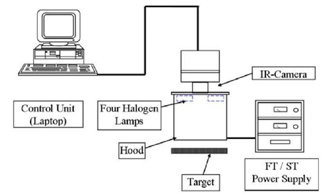
The schematic of a typical test setup is shown in Figure 1. Long pulse thermography was used to inspect composite materials with the use of SIUC’s IMEL thermography equipment. The analyses were performed on the CFRP samples. The long pulse thermography method subjected one face of a specimen to a constant and uniform heat flux, and recorded the surface temperature response on the same face. The heat source was applied for approximately 5 sec, and then the sample was allowed to cool down. The IR camera recorded the data from the start of the heat flux application and up to 5 sec after the heat flux was removed. The distance between the lamps and the sample was adjusted to approximately 18in or 460mm from the front of the specimen to the front of the IR camera. The lamps were positioned so that they would be exactly at the same distance from the sample for each experiment. Temperature data was taken every 0.03 second when the experiments were performed. All thermal response images and frame rate set-up were collected by a computer.
Figure 1: A Typical Transient Thermography System
IRT NDE Software
Current IRT system enables the capturing and processing of sixty of digital images per second. The thermal response images are typically analyzed for temperature differentiation which may indicate the suspected defects. "Noise of multiple nature and optical distortions produce difficulties for the interpretation of the recorded data. Post-processing is a powerful tool for the determination of the shapes and sizes of sub surface defects in inspected subjects. Regular thermal image analysis combined with special methods based on heat transfer theory can be applied to each IRT inspection" [9]. Several thermal data processing algorithms are currently used for enhancement of defect detection such as Thermal Signal Reconstruction (TSR), contract computations, pulse phase imaging, derivative function, and slope function. Therefore, this research developed IR NDE evaluation software with algorithms for thermal data processing, analysis of temperature-time history data, and qualitative visualization of thermal response data. The software was coded by MATLAB. Some of built-in functions used in the programs are contained in the image analysis toolbox. Approximately fifteen MATLAB subroutines were developed as part of this research for pre-processing, processing, and post-processing analysis of IRT images. The goal of this software is to detect the subsurface anomalies and provide quantitative information about defects with minimal input from the user. The screen of software as in Figure 2:
Figure 2: screen of transient infrared thermography NDE system software
Materials
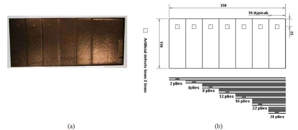
The CFRP sample is shown in Figure 3(a). The CFRP has seven embedded defects (films of Teflon) in different layers ranging from 2 plies, 4 plies, 8 plies, 12 plies, 16 plies, 22 plies, to 28 plies deep. The panel is made of different layers, the number of layers range from 2 to 32 layers of carbon fiber weave. Since CFRP are made layer by layer there is possibility that defects will occur in between the layers. The most common defects that are seen in CFRP are delaminations, voids, inclusions, porosity, and regions having non uniform distribution of fibers [10]. When the panels were laid out, Teflon inserts were placed in between some layers at known locations and sizes to represent defects, mainly delaminations. To find the range of defects that can be found, each panel had the Teflon parts inserted at different depths and sizes, each panel has different shaped defects. Figure 3(b) is schematics of the CFRP panel that were used in testing.
Figure 3: Images of commercial CFRP
Fuzzy Expert System Architecture of IRT
After the IRT inspection, testing data is processed by the intelligent IRT NDE expert system, which is implemented in MATLAB. The fuzzy logic expert system consists of two main components: The first is a set of fuzzy inference systems (FISs) (MathWorks, 2005a) and the second is an m-file (i.e. a MATLAB program (Math-Works, 2005b)). The software was coded by MATLAB because it integrates mathematical matrix with visualization capabilities and fuzzy inference functions. Some built-in functions of MATLAB executed in the programs include the image analysis and fuzzy logic tool boxes.
Input Data
The data that is inputted to the expert system consist of the IRT thermal response serious images measured by the long pulsed thermography system. Thermal response serious images are then converted to a three dimensional array (I). The data array I contains three dimensions, an area of image and time frame number with the value of temperature. For example, the value of I (100, 150, 1) means that the temperature value of the pixel of in the X-direction is 100 and the Y-direction is 150 at time frame number 1. The IRT analyzed the presence of hot spots which may specify the existence of subsurface defects. Surface emissivity effects, heterogeneous heat sources and optical distortions produce difficulties in interpretating the recorded data. In order to avoid these problems this research had to develop algorithms for determining the defects of CFRP materials. Based on the subtract function algorithm, temperature gradient data at five certain time frames were created by the IRT NDE system. The temperature gradient data at a certain time frame, data (I), is directly used as membership of the fuzzy clustering algorithm.
"In statistics, a standard score indicates how many standard deviations an observation or datum is above or below the mean. It is a dimensionless quantity derived by subtracting the population mean from an individual raw score and then dividing the difference by the population standard deviation. This conversion process is called standardizing or normalizing" [11]. In the fuzzy model for IRT fuzzy expert system, two variables were used in each time frame data set. These input variables sent to the FISs include (1) temperature gradient standard score (TGSC) value of a pixel and (2) the mean value of the temperature gradient standard score in a 3×3 pixel window. The value of the mean and standard score of the pixel is allocated to central pixel of each window.
Knowledge Base
The knowledge base of fuzzy expert system includes fuzzy set and fuzzy rules. At first, the two input variables and output variable are modeled by fuzzy sets in their respective ranges. The range of normal TGSC levels is considered to be from 0.25 to 0.75, from 0.5 to 0 it is considered low, between 0.5 and 1 it is high, a level below 0.25 is very low , and a level above 0.75 is very high. Thus, the following linguistic labels were used for the variable standard score level and the mean TGSC level: very low (VL), low (L), medium (N), high (H), very high (VH). The output variable (defect confidence level) was attributed in the following five labels: very low (VL), low (L), medium (M), high (H), very high (VH). The inference method proposed by mamdani-style inference was utilized .The output is a constant value in the range of [0, 1] for presenting the defect confidence level. The membership functions of the fuzzy sets assumed by input variables and output variable of the system are shown in Figure 4. Fuzzifier is then depicted into triangles. To increase the effect of signal amplitude and the size of the defect, this study used a number of fuzzy it-then rules. The rule-base is shown in Figure 5 and it is composed of 25 rules, like this "If standard score level is VH and mean density level is VH then defect confidence level is very high." The system output is obtained by utilizing the fuzzy rules and the fuzzy inference method. This output is a real number with a linguistic label. Complex relationships between all variables used in the fuzzy system can be represented best by the hierarchical structure shown in Figure 6.
Figure 4: Membership functions of fuzzy sets assumed by input variables and an output variable representation.
Figure 5:25 rules of the rule-base elaborated of IRT fuzzy expert system
Figure 6: hierarchical fuzzy model for IRT fuzzy expert system
Results and Discussion
Experimental Result of IRT
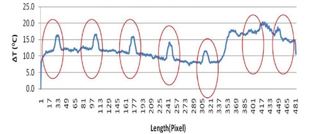
The IRT inspection was conducted on CFRP sample. Simulated defects were detected in all three samples with the use of the long pulse thermography method. The temperature profiles and defects detected are shown in Figures 7 which were captured at frame 200 and 240.An advance data processing algorithm (subtract function method, SF) was used for enhancement of signal-noise ratio of thermal images. The line profile plots are shown in Figures 8which captured frames 200. This allowed for a temperature variation to be seen within the defects
Figure 7: Thermal image on CFRP sample
Figure 7 shows defects within the CFRP sample using long pulse thermography. This sample had 1mm by 1mm square simulated defects at 2, 4, 8, 12, 16, 22, and 28 plies deep from the surface. Seven simulated defects were easily detected on two sections. Figure 8 is the thermal line profiles for the CFRP simulated defects. The graph in Figure 8 shows seven distinctive temperature changes; (1) is the square simulated defect at a depth of 2 plies, (2) is at 4 plies deep, (3) is at 8 plies deep, and (4) is at 12 plies deep, (5) is at 16 plies deep, (6) is at 22 plies deep, and (7) is at 28 plies deep.
Figure 8: Line Profile of CFRP sample
Thermography was able to detect seven embedded simulated defects sealed by resin in CFRP sample to a depth of 28 plies deep with reasonable accuracy. The distinctive temperature change for depth of 28 plies deep defect with a maximum temperature change is about 4°C ~ 5 °C. Some of the defects were not displayed clearly by a bright white spot on the IR camera, again instead it was revealed by using the thermal profile over the area. Overall, being able to find these defects is based on the operator’s experience, and improper testing and skill can result in defects not being found.
Defects Detection by IRT Fuzzy Expert System
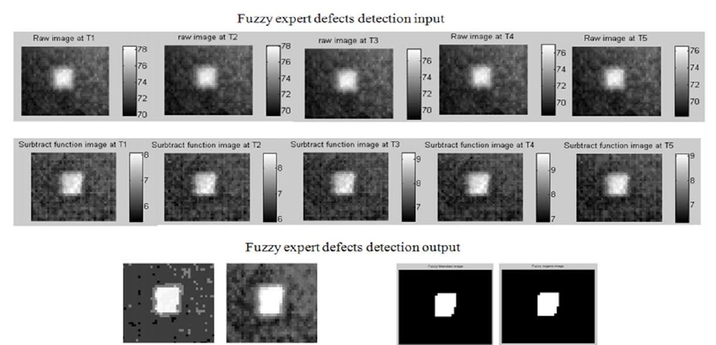
In the IRT fuzzy expert system, the specimen was used to determine the capability and performance of the system for identifying the defect’s size and shape in particular samples. This research used two fuzzy logic inference methods in the IRT fuzzy expert system which are Mamdani-style and Sugeno-style methods.
Figure 9: Fuzzy expert detected defects in CFRP sample (8 plies)
Figure 10: Detected Defects comparison in CFRP sample (28 plies)
Figure 9 shows fuzzy expert defect detection input and output images of the embedded defect in 8plies deep within the CFRP sample. Figure 10 shows the fuzzy expert defect detection input and output images of the embedded defect in 28plies deep within the CFRP sample. The spatial resolution of the sample was found to be 0.66mm/pixel. With this information the defect size can be determined for the samples tested. According to the output of IRT expert system, the dimension of the defects is around 5.94mm by 5.94 mm in square shape which are shown in Figure 9 and 10.
Conclusion
This IRT NDE logic fuzzy expert system gave plausible results for the porosity location and distribution which match well with the result of performance testing in IRT NDE method by IRT expert. This fuzzy logic expert system similar to the human eye and can be used in applications to eliminate the human errors during inspection. Also, fuzzy logic expert systems improved the inspection capability by inferring some fuzzy logic expert rules for better defect detection and noise elimination. It is recommended that further work be done on the quantitative study of the particular defect size, type, and depth in order to determine the effect of these parameters on the results using the intelligent IRT NDE expert system. Also, the accuracy and the range of this system for any specified defect condition are necessary to be investigated. The intelligent IRT NDE expert system employed in this study can be applied to building an expert system for automated detection of defects and porosity levels in commercial aerospace CFPR materials production process.


