ABSTRACT
Commercially available polycrystalline nickel (Ni200; grain size: 30 ^m) and electrodeposited nanocrystalline nickel (grain size: 30 nm) were analyzed for the phenomena of in-situ heat generation and strain localization during plastic deformation at room temperature. Tensile specimens according to ASTM E8 standard dimensions were tested at a strain rate of 10-2/s to record the amount of heat dissipated and the change of localized strain using a high resolution infrared detector and digital image correlation (DIC) camera, respectively. For deformation close to ultimate tensile strength, data recorded for the maximum temperature increase and localized strain for nanocrystalline were 110C and 4.5%, whereas polycrystalline nickel showed 170C and 60%, respectively. The amount of heat generated locally by strain is related by the heat conversion factor (i.e. Taylor Quinney coefficient). Polycrystalline nickel showed a decreasing trend of heat conversion due to lattice distortions or defect formation during deformation. In contrast, nanocrystalline nickel showed an increasing trend, likely due to differences in deformation mechanisms.
INTRODUCTION
Over the past three decades, major research efforts have been concerned with the study of the mechanical properties of nanocrystalline materials, in particular nanocrystalline metals [e.g.1,2]. For nanocrystalline metals produced by the electrodeposition methods, significant improvements in their yield strength and hardness are observed which are due to Hall-Petch grain size hardening [3]. The influence of grain size on other mechanical properties such as the Young’s modulus, abrasive and adhesive wear resistance, and coefficient of friction are also well documented [3,4]. However, many issues regarding deformation mechanisms, intrinsic ductility or strain hardening capacity of these materials still require further study.
One aspect issue that needs to be addressed is the phenomenon of in-situ heat generation and strain localization during deformation, which could have a considerable effect on the mechanical properties. Temperature increases during deformation could lead to thermal softening, which in turn could affect the failure process. It is well known [5,6] that most of the energy of plastic deformation is dissipated as heat and the remaining balance stored in the material as strain energy (e.g. lattice distortions, defect formation). For example, this subject is of interest in the study of stored energy and its effects on the process of recrystallization during deformation. In recent years, infrared imaging technology [7] combined with digital image correlation (DIC) strain measurement [8] during tensile testing have been widely used. Examples include studies on the effect of cold expansion of holes using thermoelasticity and digital correlation [9,10] and the analysis of stress distributions on turbine blades [11]. Effects of heat generation and strain localization on mechanical properties are also well documented. For example, the infrared technique has been applied successfully to study heat generation due to plastic deformation in tensile testing of TRIP steels during deformation at strain rates up to 10-1/s [12]. Results showed a maximum temperature increase of 350C within the strain hardening regime; 580C near the necking regime and 900C just before sample fracture. One particular study on strain localization using DIC acquired full-field necking behaviour of mild steel deformed at a strain rate of 10-3/s [13]. Localized strain gradually developed and built up during the deformation process. The results showed that the highest localized strain was located at the necking zone beyond ultimate tensile strength and the position of highest localized strain corresponded to the area of fracture. In another study, the rapid evolution of shear banding close to the necking region was captured with the DIC method on fully dense nanocrystalline nickel at a strain rate of 10-4/s [14].
The purpose of this study is to correlate the phenomena of in-situ heat dissipation and strain localization for both polycrystalline and nanocrystalline nickel and to analyze the coupling effect to the thermomechanical properties during plastic deformation.
EXPERIMENTAL PROCEDURE
Tensile coupons of electrodeposited nanocrystalline nickel (grain size: 30 nm) of dimensions according to ASTM E8 standard (12 cm X 2 cm X 0.1 cm) were provided by Integran Technologies Inc, Toronto. Polycrystalline nickel samples with the same size were machined from commercially available Ni 200 (grain size: 30 ^m). Prior to tensile testing, tensile samples were spray painted black on one side to equalize emissivity for better infrared detection. On the other side, samples were lightly abraded using 320 grit sandpaper for the measurement of localized strains. The high resolution infrared camera was calibrated before each experiment. Tensile samples were loaded on a MTS servo-hydraulic tensile testing machine. All samples were tested at a strain rate of 10-2/s. Temperature changes and localized tensile strain were measured simultaneously during tensile testing using a high resolution infrared camera (Deltatherm 1410) and a high resolution Digital Image Correlation Camera (Allied Vision Technologies), respectively. Temperature and strain were continuously recorded to sample fracture. However, in this paper the thermomechanical response was only analyzed up to ultimate tensile strength for each material.
RESULTS AND DISCUSSION
Polycrystalline and nanocrystalline nickel exhibit very distinct engineering stress-strain curves as shown in Fig. 1. Polycrystalline nickel has a yield strength of 208 MPa, ultimate tensile strength of 442 MPa and 50% elongation-to-fracture. On the other hand, nanocrystalline nickel shows a yield strength of 950 MPa, ultimate tensile strength of 1504 MPa and 8% elongation-to-fracture. These results illustrate that yield strength (cy) and ultimate tensile strength (curs) improve significantly when the grain size is refined to 30 ^m to 30 nm. This can be explained on the basis of the Hall-Petch grain size strengthening mechanism.
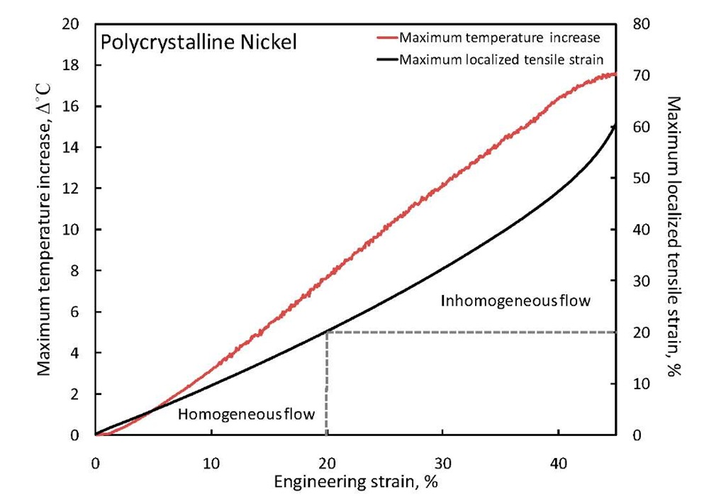
Both polycrystalline and nanocrystalline show considerable amounts of necking beyond UTS. However, polycrystalline nickel shows much higher ductility compared to nanocrystalline nickel due to the extended region of uniform plastic deformation, which can be attributed to the high intrinsic ductility of fcc materials with large grain size. Localized strain and heat distribution were measured by the DIC camera and the infrared detector, respectively, and the results of strain and heat recorded up to UTS for both polycrystalline and nanocrystalline nickel were also quite distinct (Fig. 2). Polycrystalline nickel with relatively high ductility showed noticeable changes in localized strain along the sample gauge when deformed to 25% and 45% engineering strain. The increase of localized tensile strain is highlighted by the gradual change in colour scale from dark purple and blue to bright green and yellow. At the 45% engineering strain level (i.e. just before UTS), polycrystalline nickel exhibits two regions of highly localized strain (i.e. yellow regions). One of the two regions with the highest strain levels corresponds to the position of final fracture, indicated by the dashed line in Fig. 2. On the other hand, for nanocrystalline nickel with relative high cy and cUTS, and low ductility only one high localized strain region was observed at 5.5% engineering strain (i.e. just before UTS). Such distinct behaviour of polycrystalline and nanocrystalline nickel regarding localized strain distribution is likely due to the nature of plastic flow within the uniform deformation regime. Localized strain of polycrystalline nickel (Fig. 3) showed a transition from homogeneous to inhomogeneous flow from ~ 20% engineering strain onwards. Within the region of inhomogeneous flow, the detected localized strain is higher than the engineering strain. For example, deformation at 40% engineering strain yielded 47% localized tensile strain in the region shown by the dashed line.
Fig. 1 Engineering stress-strain curves for polycrystalline and nanocrystalline nickel
Fig. 2 Localized tensile strain (top) and heat distribution (bottom) of polycrystalline (left) and nanocrystalline nickel (right) at various engineering strain levels. The dashed lines indicate the position of the final fracture planes
In contrast, nanocrystalline nickel (Fig. 4) shows that localized tensile strain is consistently lower than the engineering strain within the region of uniform deformation. For example, the deformation at 3% engineering strain in nanocrystalline nickel only yields 2% maximum localized tensile strain. This results in a relative homogeneous strain distribution observed in nanocrystalline nickel and low localized strain hardening capacity.
In addition to the localized strain, the heat distribution (Fig. 2) during deformation was also recorded by the infrared camera. Similar to the result in strain localization, polycrystalline nickel also shows noticeable changes in temperature at different engineering strain levels. With the increase of engineering strain to 25% and 45%, an increasing amount of heat is dissipated and a considerable increase of temperature is detected at the center of the gauge (dashed line). The temperature increase reached its highest point of 170C at 45% engineering strain (Fig. 3). On the other hand, nanocrystalline nickel dissipates less heat and heat distribution along the sample gauge is more uniform. At 5.5% engineering strain, the maximum temperature increase reached 110C which is lower than for polycrystalline nickel (Fig. 4). The observed temperature increase correlates with the localized strain. In other words, increasing of localized tensile strain during deformation in both polycrystalline and nanocrystalline nickel induces heat dissipation.
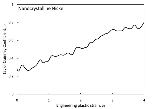
The difference in heat dissipation for the two materials could be explained by the heat conversion factor of polycrystalline and nanocrystalline nickel. According to the laws of thermodynamics, plastic work is converted to either stored energy (i.e. lattice distortions, defect formation) or to heat dissipation when metals undergo deformation process [15,16]. The fraction of heat converted from plastic work is known as the Taylor Quinney coefficient (P).
where p is the material density; Cp the heat capacity; A T the heat rate; a represents the plastic stress and e is the strain rate. In both cases of polycrystalline and nanocrystalline nickel, the heat capacity and density are constant at 480 J/mol K and 8.3g/cm3, respectively [3,17]. Different heat conversion trends were observed for polycrystalline and nanocrystalline nickel. Polycrystalline nickel shows that a decreasing amount of energy is converted to heat for increasing plastic strain to 40% (Fig. 5). In contrast, for nanocrystalline nickel the amount of plastic strain energy converted to heat increases with increasing strain (Fig. 6).
The main deformation mechanism during room temperature deformation of polycrystalline nickel is dislocation slip. On the other hand, for nanocrystalline nickel a number of potential mechanisms have been proposed, including diffusional creep, grain boundary sliding and grain rotation [1-3]. We are currently assessing the correlation between heat dissipation/defect formation for the various deformation mechanisms in these materials.
Fig. 3 The maximum temperature increase and localized tensile strain of polycrystalline nickel
Fig. 4 Maximum temperature increase and localized tensile strain of nanocrystalline nickel
Fig. 5 Taylor Quinney coefficient of polycrystalline nickel
Fig. 6 Taylor Quinney coefficient of nanocrystalline nickel
CONCLUSIONS
In situ heat generation and strain localization during plastic deformation of polycrystalline and nanocrystalline nickel are interdependent. It was shown that localized strain induced localized heat dissipation in both materials. At 45% engineering strain (at UTS) in polycrystalline nickel, 60% localized strain induced a maximum temperature increase of 170C. On the other hand, nanocrystalline nickel at 5.5% engineering strain (at UTS) yielded 4.5% localized strain which induced a maximum temperature increase of 110C. The fractions of energy converted from plastic work to heat during deformation in polycrystalline nickel decreased with increasing deformation, which resulted in 80% of plastic work contributing to lattice distortions or defect formation at UTS. On the other hand, most of the plastic work in nanocrystalline nickel at UTS is converted to heat.


