The small multifunction routers shown in that topic’s SOHO figures connect a home or small office’s subnets to each other — and to the Internet. These small routers can forward packets at a rate ranging from 10 to 20 megabits (millions of bits) per second. That seems plenty fast, but get this: Routers for large private networks (major corporations and organizations) have to be able to forward tens of millions of packets per second. Routers for the Internet forward hundreds of millions of packets per second. Oh, by the way, these big-to-huge routers also cost big-to-huge amounts of money.
No matter how many networks are attached, the router’s job never changes: It connects networks. We can’t say it enough. The job may get more complicated, though, when a router has to figure out where and how to send millions of packets. Special routing protocols help the large routers do their complex jobs.
This topic introduces some of the added functions, protocols, and terminology associated with the big routers.
Understanding Routing Lingo
Routing and routing protocols have a jargon all their own. Before devouring the meat of this topic, here are some bite-size definitions that make the reading easier:
✓ Packet switching: The TCP transport layer divides messages into packets before they move out onto a network. Routers use packet switching to move messages from one place to another on a network. During transmission, each packet is independent of the others. In fact, each packet in a message could take a different route to the destination. That’s packet switching. The point is that all the packets in a message get to the destination, not how they get there. In Figure 8-1, the packets from the original message travel by different paths to the same destination. TCP reassembles the packets.
Figure 8-1:
Packet switching delivers packets to the right place and rebuilds the message.
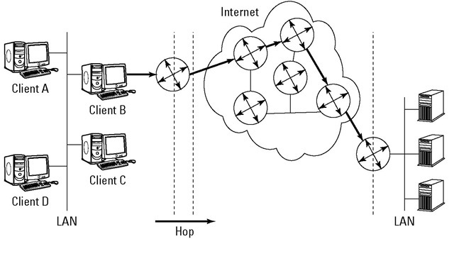
✓ Routing: Routing is the process of forwarding a packet to a destination IP address. The router decides how to forward the packet. The route is the path to the destination IP address. One way of measuring the efficiency of the route is in hops.
✓ Hop: A hop is each leg of the journey that a packet takes on its route. No, it’s not because the packet has to jump on one leg. In the network shown in Figure 8-2, the lines between the routers represent hops. Not every router connects directly to another, so the hop count is one or sometimes more than one. For example, the direct path from router A to G is one hop. Router A could also hop to router H and hop again to router G. A packet could also hop around the outside the network — A to B, B to C, and so on.
✓ Routing table: Routers try to determine the most direct route that is also the most trustworthy route. The router checks a lookup table, called a routing table, which stores routes for data to travel. The router gets most of its intelligence from routing tables. Routing tables contain information about the following:
• Paths (routes) to particular networks
• How to handle special kinds of traffic
• Priorities for certain connections
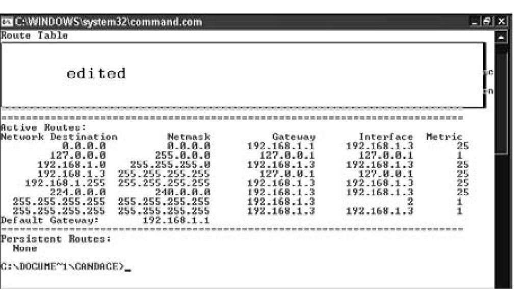
On big fancy routers, the routing tables also store statistics on which routes are fastest and shortest. You can use the command netstat -rn in Mac OS X, Linux/Unix, or Windows to display the routing table for your computer. The netstat command option -r means to show the routing table. The option -n means to display the addresses in numeric form. The routing table shown in Figure 8-3 is a small IPv4 table from Windows 7. Because Windows 7 runs a dual stack, there is a separate routing table for IPv6 destinations.
Figure 8-2:
A packet can hop along different routers to reach the same destination.
How the cold war gave us dynamic routing
TCP/IP has its origins in the United States agency, DARPA (Defense Advanced Research Projects Agency) in the 1960s. In those days of the Cold War, the U.S. was worried about the threat of nuclear attack. DARPA’s job was to design a way to connect computers and maintain the connection even if the network was disrupted. For example, if a network segment was taken out by enemy attack, the traffic on that segment would automatically move to another network segment. This reliable scheme is call dynamic routing. Eventually, this network became the ARPANET, where TCP/IP was born. Complex routing protocols weren’t needed back then because the ARPANET could only support 256 networked computers. Of course, the ARPANET gradually morphed into the Internet, with its mammoth traffic, and now routing protocols are a big deal. Your system doesn’t have to be a victim of an enemy attack for dynamic routing to be valuable. Thanks to dynamic routing, if a forklift cuts a cable in a warehouse inventory and blocks one route, data can take a different route across the network.
Figure 8-3: netstat -r shows an IPv4 routing table on a Windows 7 host.
To display the IPv6 routing table, you need to use the netsh command:
1. Open a command window.
2. Type netsh at the command prompt. Press Enter.
3. Type interface ipv6 at the prompt. Press Enter.
4. Type show routes. Press Enter.
The netstat command can show you a lot more than the routing table on your machine. It can also display all your computer’s network connections, ports, protocols, and Ethernet statistics. Netstat can be a helpful diagnostic tool when you need to know what processes and programs are active on your network. You can also use netstat to monitor network communications, looking for malware running. You can specify that the netstat display updates itself at a regular interval so you can watch your network statistics change.
Starting TCP/IP automatically creates a routing table. You can add more entries either manually or automatically.
✓ Routing protocols: Routing protocols are the rules routers follow to send packets on their way. The protocols specify how a router should figure out a path to send packets. The protocols also spell out whether the router can change its mind about a route (dynamic routing) or whether it should stick with pre-set routes (static routing).
✓ Metrics: Routers use statistics called metrics to choose the fastest and most reliable route for a packet to travel. Some metrics include
• Bandwidth: The data-transfer rate between two points on a network.
• Delay: The time it takes for a packet to get from its source network to its destination network.
• Reliability: The error statistics for a router or network segment to travel.
Routing Through the Layers — the Journey of a Packet
Packets go up and down the TCP/IP layers as they travel from one location to the next. Let’s say you want to initiate a Google search. The browser running on your PC — the source computer — needs to send a message to the Web server running on www.google.com — the destination computer — in order to get Google’s home page. There’s going to be a lot of layer travel involved. Figures 8-4 through 8-8 display a packet’s travel through the network layers, to and from routers, until it reaches its final destination. We also provided a list of the steps that the packet travels until it reaches its final destination, shown later, in Figure 8-8.
A new message heads out across the Net
These first steps occur on the source computer, your PC. Figure 8-4 illustrates how the request starts on your computer at the application layer. The following text describes Steps 1 through 6 in detail:
1. (Application Layer – outbound) Begin to construct the message.
The data in the message is a simple HTTP Get request. The source address is your computer’s FQDN (fully qualified domain name). The destination address is the FQDN www.google.com.
Figure 8-4:
The message starts at the application layer of your computer (the source).
2. (Transport Layer – outbound) Choose TCP or UPD; add the source and destination port numbers.
TCP is connection-oriented, provides error detection, and ensures that the message arrives at its destination. UDP is connectionless, generally doesn’t check for errors, and doesn’t ensure that the message arrives. Your message uses TCP.
Because many applications can be running on the same server (that is, mail server, Web server, file sharing, and so on), they listen on different TCP/IP ports. Every server application has a default port number, in fact it often has 2 — one for non-secure and one for secure communication. For example, a Web server normally listens on the default ports 80 and 443. This outbound HTTP request needs to specify port 80.
When the response finally arrives, it needs to be delivered to your Web browser (not your e-mail client or any other application you’re running), so the message sets a source port number. (The actual port number isn’t important the way it is for a service.)
3. (Internet Layer – outbound) Replace the names with their IP addresses.
Because computers talk to each other using numbers rather than names, the message needs the IP addresses rather than the FQDNs. In this example, the IP address of your computer is 192.168.0.2, and the IP address of www.google.com is 64.233.169.147. (Actually, there are multiple addresses for www.google.com because there are multiple servers handling the workload of Google searches.)
4. (Data Link Layer – outbound) Set the MAC (Media Access Control) addresses.
If the destination computer was on your local intranet, your PC could send the message directly there. Because the destination computer in this example is not local, your PC doesn’t know how to get the message there. The best it can do is to send the message in the right direction — to a local router. As part of its TCP/IP configuration, every computer has a default route. (It’s also known as a default gateway.)
In either case, local destination or not, the IP addresses aren’t enough information. The message needs the MAC addresses:
• The source MAC address is set to the hardware address of the NIC that forwards the message.
• The destination MAC address is the hardware address of the NIC that receives the message.
In this example, even though you’re going to Google, you’ll have several destinations along the way. At this stage, the destination MAC address is your local router’s intranet NIC.
5. (Physical Layer – outbound) Pick a NIC.
"Which of my NICs should I use?" your PC asks itself. If it has multiple NICs, it selects the correct one — the one that communicates with the local router. (Because it has only one, the choice is simple.)
6. Send the message.
This is the first hop along the route.
The message visits the router
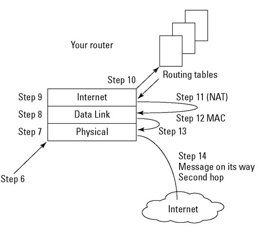
The message travels across the transmission medium and arrives at your local router. These next steps take place there. The next steps occur at the router’s bottom three layers. Figure 8-5 illustrates Steps 7 through 14: how the router receives and processes the request, and then consults routing tables and the MAC address to determine how to forward the message on the next part of its journey.
Here are the router Steps 7 through 14:
7. (Physical Layer – inbound) Receive the message.
"Oh, look! A message," your local router says.
8. (Data Link Layer – inbound) The MAC address in the message matches the NIC’s.
"Hey. This message is addressed to me!" your local router continues.
9. (Internet Layer – inbound) Which computer is this message for?
Your local router examines as few bits as possible in the destination IP address until it can decide what to do with the message. For example: "Wait a minute! This IP address starts with 64. That’s not one of my intranets. I need to send this message on its way."
Figure 8-5:
The message moves on to its second hop.
10. Your local router consults its routing tables.
Your local router picks the appropriate routing-table entry, or its default route if necessary. The entry tells your local router the best path for the next hop.
11. (Internet Layer – outbound) Adjust the IP addresses?
Because this router is also performing NAT (Network Address Translation), it replaces the source IP address — your PC’s non-routable IP address — with the router’s own external IP address. The destination IP address remains the same.
When the response finally arrives, your local router reverses this action. It replaces its own external IP address with your computer’s IP address.
12. (Data link Layer – outbound) Set the MAC (Media Access Control) addresses.
Because the destination computer in this example is still not local, the router sends the message in the right direction. It sets the source MAC address to the MAC address of the NIC that will forward the message. The destination MAC address is an Internet router’s NIC.
13. (Physical Layer – outbound) Pick a NIC.
"Which of my NICs should I use?" your local router asks itself. It selects the correct one — the one that communicates with the selected Internet router.
14. Send the message.
This is the second hop along the route (refer to Figure 8-5).
Into an Internet router and out again
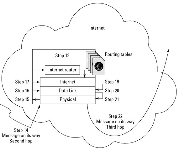
The message travels across the transmission medium and arrives at an Internet router. These next steps repeat for each hop that takes the message from one Internet router to another. For this example, there is just one hop because the next router is the one that can reach Google’s router: Steps 15 through 22 describe the message’s movements at the Internet’s router. The message only travels through the bottom three layers of the Internet router (just as it did at the local source’s router). Figure 8-6 summarizes the steps the message passes through on an Internet router:
15. (Physical Layer – inbound) Receive the message.
"Oh, look! A message," the Internet router says.
16. (Data Link Layer – inbound) The MAC address in the message matches the NIC’s MAC address.
"Hey. This message is addressed to me!" the router continues.
17. (Internet Layer – inbound) Which computer is this message for?
The Internet router examines as few bits as possible in the destination IP address until it can decide what to do with the message. "This address starts with 64. That’s not one of my intranets. I need to send this message on its way."
18. The Internet router consults its routing tables.
The Internet router picks the appropriate routing-table entry. The entry tells the Internet router the best path for the next hop.
19. (Internet Layer – outbound) Adjust the IP addresses?
The Internet router leaves the IP addresses alone. "This message didn’t come from any of the computers on my intranets, and it’s not going to any of the computers on my intranets so the IP addresses are none of my business."
20. (Data Link Layer – outbound) Set the MAC (Media Access Control) addresses.
Because the destination computer in this example is still not local, the Internet router sends the message in the right direction. It sets the source MAC address to the MAC address of the NIC that will send the message onward. The destination MAC address is the NIC of the next router. In this example, the next router is Google’s.
21. (Physical Layer – outbound) Pick a NIC.
"I better use the NIC that talks to Google’s router," the Internet router decides.
22. Send the message.
This is the next hop along the route.
Figure 8-6:
The message moves through a router on the Internet and goes on its way to a google.com router.


