This topic discusses remote sensing in the visible EM spectrum, beginning with images and technology from the first remote sensing satellites (the Corona spy satellites) and concluding with a look at several optical imaging satellites, particularly the Hubble Space Telescope (HST).
A little history
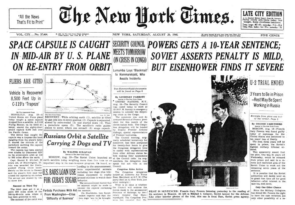
Corona was America’s first operational space-reconnaissance project. It was developed as a highly classified program under the joint management of the CIA and USAF, a relationship that evolved into the National Reconnaissance Office (NRO). For context, note that the first Soviet satellite, Sputnik, was launched on October 14, 1957, and Van Allen’s Explorer spacecraft flew on a Redstone rocket on January 31, 1958. President Eisenhower approved the Corona program in February 1958. This proved to be farsighted, because when Francis Gary Powers was shot down in a U-2 on May 1, 1960, the president was forced to terminate reconnaissance flights over the Soviet Union (see the newspaper in Fig. 3.1).
The first Corona test launch, on February 28, 1959, was the first of 12 failed missions in the Discover series (a cover name)—seven involving launch, five involving satellite and camera malfunctions. Mission 13 yielded the first successful capsule recovery from space on August 10, 1960.1 The first high-resolution images from space were taken on the next mission, August 18, 1960.
Figure 3.1 The New York Times, August 20, 1960. Note the other headlines at this time.
The last Corona mission, number 145, was launched May 25,1972; the last images were taken May 31, 1972. Curiously, signals intelligence got a slightly earlier start; the launch of the first GRAB satellite on June 22, 1960, launched the electronic intelligence discipline into space.
Early imaging resolution was on the order of 8-10 m, eventually improving to 2 m (6 ft). Individual images on average covered approximately 10 miles by 120 miles. The system operated for nearly 12 years, and over 800,000 images were taken from space. The declassified image collection includes 2.1 million ft of film in 39,000 cans. The subsequent KH-7 mission acquired imagery with resolutions of 2-4 ft beginning in July 1963, with much smaller imaging areas.3
The technology
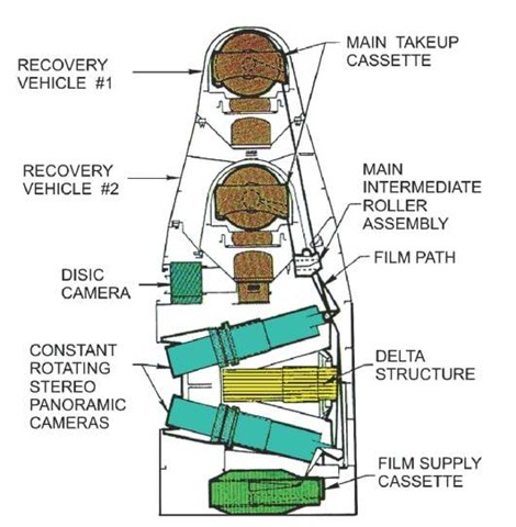
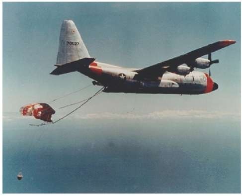
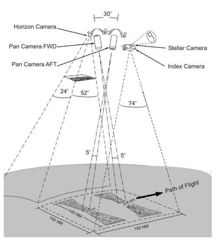
The Corona concept was to use film cameras to record images for a few days, then drop the film using a recovery vehicle. The film containers were de-orbited and recovered by Air Force C-119 (and C-130) aircraft while floating to Earth on a parachute. The system adapted aerial-photography technology with a constantly rotating, stereo, panoramic-camera system [Figs. 3.2(a), 3.2(b), and 3.3]. The low orbital altitudes (typically less than 100 miles), and slightly elliptical orbits eased some of the problems associated with acquiring high-spatial-resolution imagery. The "Gambit" series of KH-7 satellites flew at even lower altitudes with initial perigees as low as 120 km.
The cameras, codenamed "Keyhole," began as variants on products designed for aerial photography. The first cameras, the "C" series, were designed by Itek and built by Fairchild. Two counter-rotating cameras, pointing forward and aft and viewing overlapping regions, allowed for stereo views (Fig. 3.4). The cameras used long filmstrips, 2.2 in. X 30 in., and anf75.0 Tessar lens with a focal length of 24 in. The first images had a ground resolution of 40 ft, based on a film resolution of 50-100 lines/mm. (Advances in film technology by Kodak were some of the most important technological advances in the Corona program. Kodak developed a special polyester base to replace the original acetate film.)
Improved camera, lens, and film design led to the KH4 series cameras, with Petzval f73.5 lenses, still at 24 in. focal length. With film resolutions of 160 lines/mm, it was possible to resolve ground targets of 6 ft. Corona (KH4) ultimately used film ranging in speeds from ASA 2 to 8—only a few percent of the sensitivity, or speed, of consumer film. This is the tradeoff for high film resolution and one reason that very large optics were needed.5
The great majority of Corona’s imagery was black and white (panchromatic). Infrared film was flown on Mission 1104; color film was flown on Missions 1105 and 1108.6 Photo-interpreters did not like the color film, however, because resolution was lower. Tests showed color as valuable for mineral exploration and other Earth resources studies, and its advantages led indirectly to the Landsat satellites.
Note that the Soviet Union has maintained a film-return reconnaissance technology. Russia launched Kosmos 2410, a film return system, on September 24, 2004. The satellite was launched at an inclination of 67.12° with perigee on the order of 200 km, apogee of about 300 km. The satellite lifetime is only a few months at those altitudes.
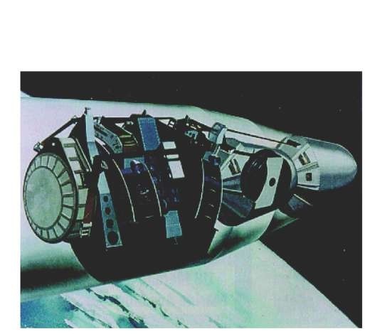
Figure 3.2(a) KH4B, artist’s concept.
Figure 3.2(b) KH4B or J3 camera. DISC Dual Improved Stellar Index Camera.
Figure 3.3 A U.S. Air Force C-119, and later, a C-130 (shown here) modified with poles, lines, and winches extending from the rear cargo door captures a capsule ejected from a Discoverer satellite. Reportedly, this was considered by some to be the least likely part of the whole process—catching a satellite in midair.
Figure 3.4 The KH4B cameras operated by mechanically scanning to keep the ground in focus. The paired cameras provided stereo images, which are very helpful for estimating the heights of cultural and natural features.
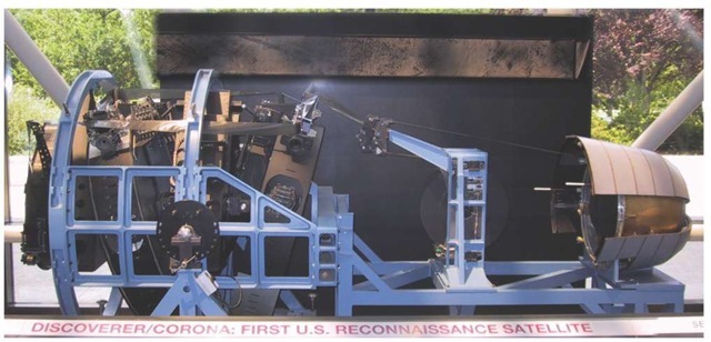
Figure 3.5 Corona satellite in the Smithsonian. The recovery vehicle is to the right.
Some illustrations
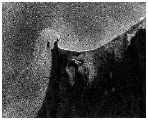
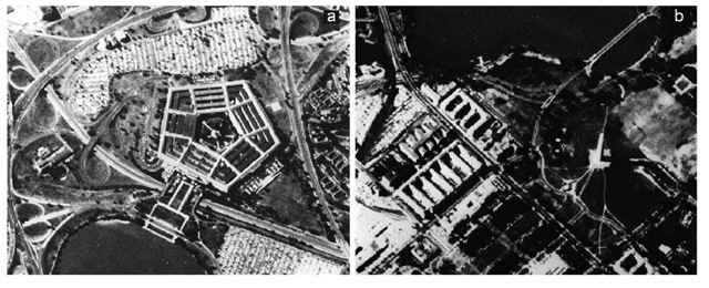
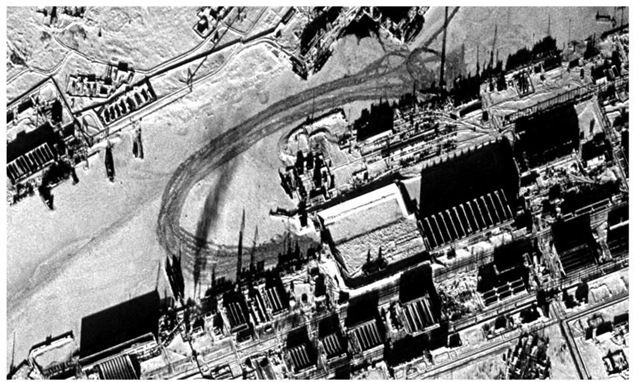
The first Corona image was taken of the Mys Shmidta airfield. Figure 3.6 shows that the resolution was high enough to discern the runway and an adjacent parking apron. Eventually, systems got better, and higher resolution images were acquired. Figure 3.7 shows two relatively high-resolution images of the Pentagon and the Washington monument in Washington DC. Declassified imagery is available from the U.S. Geological Service (USGS).9 Of course, the whole point was to spy on the Soviet Union. Figure 3.8 shows the Severodvinsk Shipyard, a North Sea port for the USSR, on February 10, 1969. The large rectangular building in the center is the construction hall, and the square courtyard to its left is where vessels (submarines) are launched. The curved trail of disturbed snow and ice is where submarines are floated into the river. The satellite is on a southbound pass over the port facility.
Figure 3.6 Mys Shmidta Airfield, USSR. This August 18,1960, photograph is the first intelligence target imaged from the first Corona mission. It shows a military airfield near Mys Shmidta on the Chukchi Sea in far northeastern Russia (Siberia, 68.900°N 179.367°W just across some forbidding water from Barrow, Alaska, at very similar latitude). North is at upper left. Credit: National Reconnaissance Office (NRO).
Figure 3.7 Washington DC. (a) One always-popular target: the Pentagon. September 25, 1967. (b) Notice the shadow cast by the Washington Monument in September 1967. Credit: NRO.
Figure 3.8 Severodvinsk Shipyard, February 10, 1969, Corona (KH4).
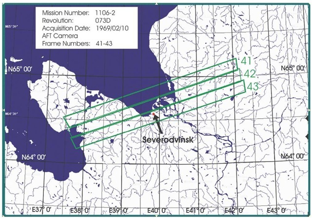
The image of Severodvinsk is a chip from a much larger scene shown in Figs. 3.9 and 3.10. The strips are perpendicular to satellite motion, which in this frame must have been towards the southeast. Note the horizon images on the edges of the film strips, showing the rounded Earth. These images from the horizon cameras provided reference/timing information as the system scanned from horizon to horizon.
Figure 3.9 Coverage map for Corona. Map derived from USGS.
Figure 3.10 Three consecutive Corona images. The shipyard in Fig. 3.8 is in the third frame, just under the word "Severodvinsk." Note the ends of the film strips: "When the satellite’s main camera snapped a picture of the ground, two small cameras took a picture of the Earth’s horizon at the same time on the same piece of film. The horizon cameras helped interpreters calculate the position of the spacecraft relative to the Earth and verify the geographical area covered in the photo."
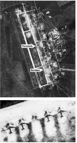
Figure 3.11 (a) The arrows indicate the number of bombers compared to transport planes. (b) An image chip for the bombers indicated in the figure is displayed here. Credit: NRO.
Figure 3.11 shows illustrations of a Soviet airfield, and a good example for AOB. This Corona mission on August 20,1966, captured an image of Soviet heavy bombers at Dolon airfield in the Soviet Union. The 5-10 foot ground resolution of the Keyhole camera systems was sufficient to distinguish classes of aircraft, allowing them to be counted. Some indications of readiness state can be obtained by the locations of the aircraft and activity around the airframes.
