EM radiation that impinges upon matter is called incident radiation. For the Earth, the strongest source of incident radiation is the sun. Such radiation is called insolation (a shortening of incoming solar radiation). The full moon is the next strongest source, but its radiant energy is only about a millionth that of the sun.
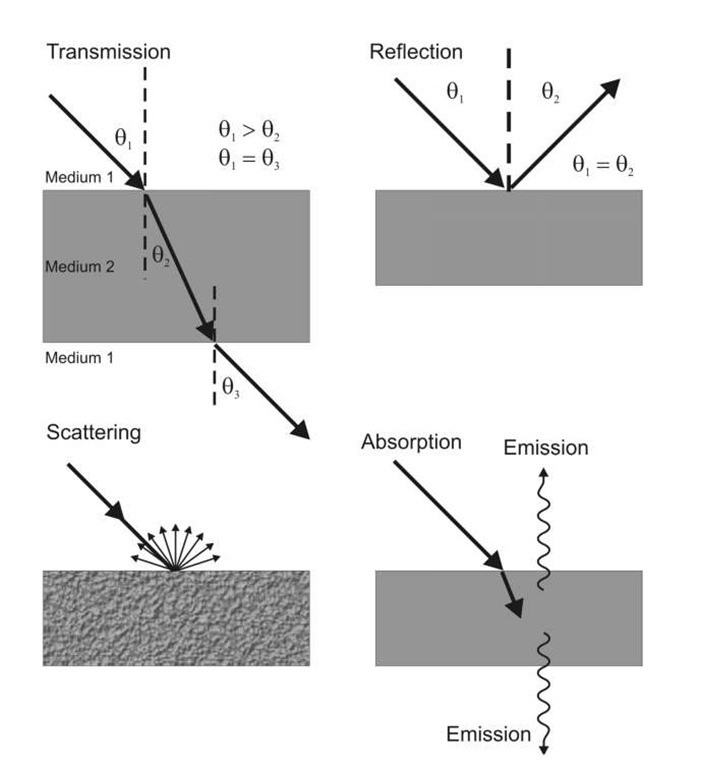
Figure 2.15 The four interactions defined here are somewhat artificial from a pure physics perspective, but are nonetheless extremely useful.
Upon striking matter, EMR may be transmitted, reflected, scattered, or absorbed in proportions that depend upon:
• the compositional and physical properties of the medium,
• the wavelength or frequency of the incident radiation, and
• the angle at which the incident radiation strikes a surface.
These four fundamental energy interactions with matter are illustrated in Fig. 2.15.
Transmission
Transmission is the process by which incident radiation passes through matter without measurable attenuation; the substance is thus transparent to the radiation. Transmission through material media of different densities (e.g., air to water) causes radiation to be refracted or deflected from a straight-line path with an accompanying change in its velocity and wavelength; frequency always remains constant. In Fig. 2.15, it is observed that the incident beam of light (01) is deflected toward the normal in going from a low-density to a denser medium![]() Emerging from the far side of the denser medium, the beam is refracted from the normal
Emerging from the far side of the denser medium, the beam is refracted from the normal![]() The angle relationships in Fig. 2.15 are
The angle relationships in Fig. 2.15 are![]()
The change in EMR velocity is explained by the index of refraction (n), which is the ratio between the velocity of EMR in a vacuum (c) and its velocity in a material medium (v):
The index of refraction for a vacuum (perfectly transparent medium) is equal to 1, or unity. Because v is never greater than c, n can never be less than 1 for any substance. Indices of refraction vary from 1.0002926 for the Earth’s atmosphere to 1.33 for water to 2.42 for diamond. The index of refraction leads to Snell’s Law:
Reflection
Reflection (also called specular reflection) describes the process whereby incident radiation bounces off the surface of a substance in a single, predictable direction. The angle of reflection is always equal and opposite to the angle of incidence![]()
![]() in Fig. 2.15). Reflection is caused by surfaces that are smooth relative to the wavelengths of incident radiation. These smooth, mirror-like surfaces are called specular reflectors. Specular reflection causes no change to either EMR velocity or wavelength.
in Fig. 2.15). Reflection is caused by surfaces that are smooth relative to the wavelengths of incident radiation. These smooth, mirror-like surfaces are called specular reflectors. Specular reflection causes no change to either EMR velocity or wavelength.
The theoretical amplitude reflectance of a dielectric interface can be derived from electromagnetic theory and can be shown to be11
where ± corresponds to E being polarized perpendicular to the plane of incidence and ||corresponds to E being polarized parallel to the plane of incidence.
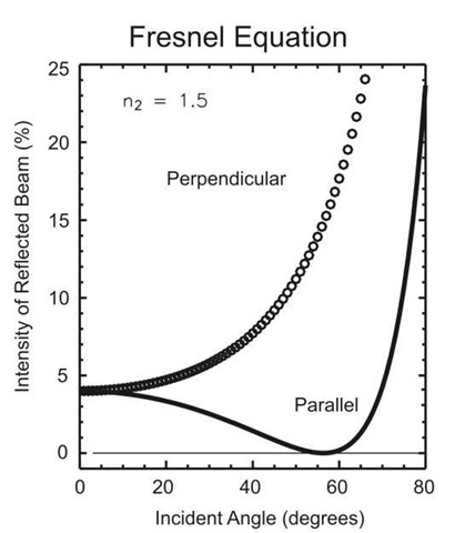
Here![]() are the refractive indices and angles of incidence and refraction in the first and second media, respectively. (Snell’s law defines 62; other versions of these equations can be obtained as a function of the incident angle, but they are more tedious to present.) Here, r is the ratio of the amplitude of the reflected electric field to the incident field. The intensity of the reflected radiation is the square of this value. Figure 2.16 shows the intensity as a function of incident angle for typical air-to-glass values of the index of refraction. The difference between these numbers is why light reflected from surfaces like water becomes highly polarized.
are the refractive indices and angles of incidence and refraction in the first and second media, respectively. (Snell’s law defines 62; other versions of these equations can be obtained as a function of the incident angle, but they are more tedious to present.) Here, r is the ratio of the amplitude of the reflected electric field to the incident field. The intensity of the reflected radiation is the square of this value. Figure 2.16 shows the intensity as a function of incident angle for typical air-to-glass values of the index of refraction. The difference between these numbers is why light reflected from surfaces like water becomes highly polarized.
Scattering
Scattering (also called diffuse reflection) occurs when incident radiation is dispersed or spread out unpredictably in many directions, including the direction from which it originated (Fig. 2.15). In the real world, scattering is much more common than reflection. Scattering occurs with surfaces that are rough relative to the wavelengths of incident radiation. Such surfaces are called diffuse reflectors. The velocity and wavelength of electromagnetic waves are not affected by scattering.
Variations in scattering manifest themselves in varying characteristics in the bidirectional reflectance distribution function (BRDF). For an ideal, Lambertian ![]() surface, this function would nominally be a cosine curve, but the reality generally varies quite a bit. Aside from the world of remote sensing, BRDF (also rendered BDRF) is also much studied in computer graphics and visualization.
surface, this function would nominally be a cosine curve, but the reality generally varies quite a bit. Aside from the world of remote sensing, BRDF (also rendered BDRF) is also much studied in computer graphics and visualization.
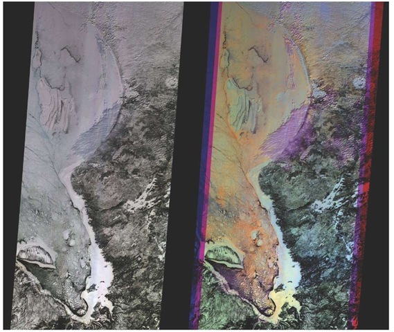
Figure 2.17 shows consequences of the variation in the scattering function from the NASA Terra satellite, orbiting at 700 km altitude, and the Multiangle Imaging Spectroradiometer (MISR). At left is a "true-color" image from the downward-looking (nadir) camera on MISR. This image of a snow-and-ice-dominated scene is mostly shades of gray. The false-color image at right is a composite of red-band data taken by the MISR’s forward 45.6°, nadir, and aft 45.6° cameras, displayed in blue, green, and red colors, respectively. Color variations in the right image indicate differences in angular reflectance properties.
Figure 2.16 Fresnel equations. Both curves approach 1 (100% reflection) as the incident angle approaches 90°. Note that there is a range of incident angles for which the intensity of the parallel component is very small.
Figure 2.17 Multiangle imaging spectroradiometer (MISR) images of Hudson Bay and James Bay, Canada, February 24, 2000. This example illustrates how multiangle viewing can distinguish physical structures and textures. The images are about 400 km (250 miles) wide with a spatial resolution of about 275 m (300 yards). North is toward the top. Photo credit: NASA/GSFC/JPL, MISR Science Team (PIA02603).
The purple areas in the right image are low clouds, and light blue at the edge of the bay is due to increased forward scattering by the fast (smooth) ice. The orange areas are rougher ice, which scatters more light in the backward direction.
Absorption
Absorption is the process by which incident radiation is taken in by a medium. For this to occur, the substance must be opaque to the incident radiation. A portion of the absorbed radiation is converted into internal heat energy, which is subsequently emitted or reradiated at longer thermal infrared wavelengths.


