Introduction
As you may recall in an earlier section on horsepower, a worker had to apply a certain amount of torque and horsepower to raise the elevator. The job would have been much easier if some sort of gearing device was applied to the crank, thereby changing the ratio of one revolution of the pulley. Mechanical devices such as belts, sheaves, pulleys, and gear boxes allow this change in ratio.
An easy place to start the discussion of ratios is the common 15-speed bicycle (Figure 2-50).
To get enough torque to start the bicycle in motion, the rider would place the gears into first gear. Notice that the rear wheel sprocket (first gear sprocket) is smaller than the pedal sprocket.
This means that the rear gear sprocket would make five revolutions compared with one revolution of the pedal sprocket. As seen in Figure 2-50,
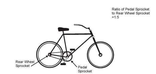
Figure 2-50. Gear ratios—first gear
first gear indicates a 1:5 ratio (one revolution of the driving shaft, in this case the pedal) compared with five revolutions of the output shaft (rear wheel sprocket).
If we assume that the rider did not place the bicycle into first gear and tried to start out in fifteenth gear, we would have a scenario seen in Figure
2-51.
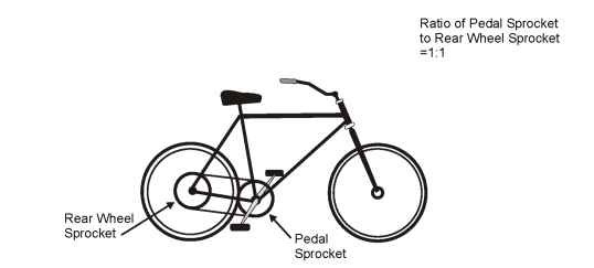
Figure 2-51. Gear ratios—fifteenth gear
As seen in Figure 2-51, the ratio of the rear sprocket to the pedal sprocket has changed to 1:1. Basically there is no mechanical advantage for the rider and therefore no reason to own a 15-speed bicycle. Essentially, the gear arrangement on a bicycle reduces the amount of reflected inertia to the pedal sprocket. This makes the job of starting the bicycle in motion much easier, with less torque applied by the rider. We could consider this action that of breakaway torque required to start the system in motion.
The only item that changed in this example is the amount of inertia reflected back to the pedals, by way of the gears. The weight and inertia of the rider remained constant, no matter what gear was selected. We will use these same principles and apply them to the following power transmission devices.
Belts and Pulleys
Flat and V-Belts
A common arrangement for belt-pulley type transmission systems is the flat belt shown in Figure 2-52. Belt-pulley arrangements are sometimes called belt-sheave, meaning that there is more than one pulley attached together, giving several selections of gear ratios.
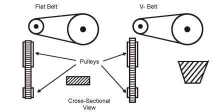
Figure 2-52. Belt-pulley arrangements
For smaller pulley diameters, the flat belt provides low weight and inertia to the power system. A disadvantage of the flat belt is that they rely on maximum friction with minimum slippage to function properly.
The v-belt arrangement allows more surface area with the inside of the pulley, which increases the friction capability (Figure 2-51). V-belts provide shock absorption between the drive and driven shafts due to its inherent v-shaped design. According to some machinery designers, a speed ratio of 7:1 is satisfactory for a v-belt system. Most flat and v-belts are constructed of nylon or durable fibers imbedded in rubber.
Both these types of systems require a certain amount of friction to operate properly. In many cases, some type of tensioning device (spring arrangement) is used to keep the belts tight and efficiency at maximum.
In some applications, a precise belt system is needed. A specific revolution in the driven shaft would produce a specific revolution in the output shaft, with little to no slippage to reduce efficiency. This type of belt system would be the synchronous belt system.
Synchronous Belts
The synchronous belt system is sometimes known as the timing belt system and is shown in Figure 2-53.
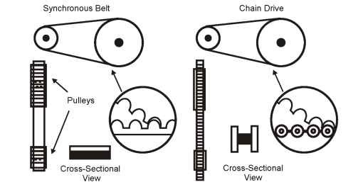
Figure 2-53. Synchronous belts system
The synchronous belt system is basically a flat belt with a series of evenly spaced teeth on the inside of the belt. This system provides the advantages of a belt, with positive grip features and little slip.
Chains and Sprockets Chain Drive
Chain drives are often used in the same manner as synchronous belts and provide positive synchronization between transmission shafts, especially when large amounts of torque are required (Figure 2-53).
The stretching action of belt systems is not a problem for a chain drive. However, depending on the number of teeth in the drive gear sprockets, slight pulsations (whipping action) could occur in the drive gear sprockets. This can cause a noise or vibration problem if the pulsations are great enough.
Couplings, Gearboxes, and Speed Reducers
In many cases, some positive method of connecting two shafts together is required when the shafts operate along the same centerline. The two most common types of couplings are rigid and flexible couplings.
The two most common types of rigid coupling are the flange and the sleeve
type.
Flange Coupling
As the name would imply, the flange type uses two metallic flanges slipped over the ends of the two shafts and bolted together. Each individual flange is either pressure fit over the shaft keyway, or locked onto the shaft by some other method such as a set screw (Figure 2-54).
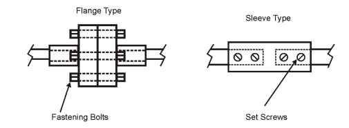
Figure 2-54. Flange and sleeve-type couplings
Flexible Couplings
The function of the flexible coupling is the same as the rigid coupling. The difference between the two is the flexing or twisting capability of the coupling parts (within limits).
A certain amount of flexing is expected with this type of coupling. Flexing may be caused by: misalignment of the shafts, shaft end movement due to insufficient motor and machine mounting, or simple vibration between the connected devices.
The flexible part of the coupling could be considered a “mechanical fuse.” If the flexible part fails, it is a sign of mechanical drive trouble in the system. The mechanical system should be thoroughly checked out before the flexible part is replaced, which is the same for an electrical system replacement. We will take a brief look at the two types of flexible couplings: mechanically flexible and elastically flexible.
Mechanically Flexible
These types of couplings obtain their flexibility from the rolling or sliding of the mating parts. As expected, these parts do require some type of periodic lubrication. Typical examples are gear, chain, and sprocket and disc types, shown in Figure 2-55.
Elastically Flexible
This type of coupling (sometimes referred to as elastomeric) obtains its flexibility from the stretching or compressing of a material such as rubber or plastic. The sliding or flexing that takes place is minimal, and lubrication is not required. These types of couplings come in designs such as jaw, clamped, or unclamped donut, and the tire (Figure 2-56).
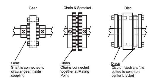
Figure 2-55. Mechanically flexible couplings
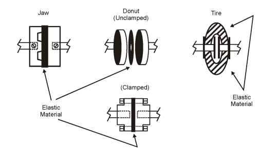
Figure 2-56. Elastically flexible couplings
Gearboxes and Speed Reducers
Gearboxes and speed reducers transmit mechanical power from the motor shaft to the driven load. A simple speed reducer contains two different sized gears, called spur gears. Spur gears are straight teeth cut parallel to the axis of rotation. Speed reducers may have more than two gears, which provide several fixed speed outputs. If that is the case, some type of clutch arrangement will exist to change gears. Figure 2-57 shows the gear relationship within a speed-reducer case.
As seen in Figure 2-57, this type of device provides an efficient means of transmitting positive speed, direction, and torque. In many cases, this device will change speed, with a corresponding change in torque or output
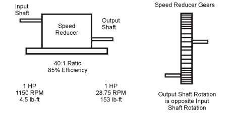
Figure 2-57. Speed-reducer characteristics
direction. The gear reducer acts as a torque amplifier, increasing the torque output by a factor proportional to the ratio, less an efficiency factor.
As seen in Figure 2-57, if a 1150-rpm motor delivers 4.5 lb-ft of torque to the input shaft, then 153 lb-ft of torque is present at the output shaft (given the efficiency of 85%). The formula used is lb-ft x reducer ratio x efficiency of the speed reducer. Therefore, 4.5 x 40 x 0.85 = 153 lb-ft of output torque.
To change the output speed by more than one fixed ratio, more than two gears are required. The same is true if the direction of rotation of the output shaft needs to be identical to that of the input shaft. The type of gear used depends on the application (i.e., horizontal axis of rotation, vertical to horizontal axis of rotation, etc.). Figure 2-58 shows several types of gears used in common speed reducers.
As shown in Figure 2-58, the speed reducer is operating at 85% efficiency. A brief look at mechanical efficiency would be helpful in understanding the actual output of the device. As previously stated, efficiency is the ratio of output power to input power and is expressed in a percent. Therefore the formula for efficiency would be:
![]()
When considering the efficiency of a belt type of device, the more friction available, the less slippage that occurs, and the higher the efficiency. The output shaft turns simultaneously with the input shaft.
In belt systems, several factors aid in decreasing total system efficiency: (1) Losses that occur due to friction of the rubber and cords as the belt stretches and flexes. (2) Friction of the belt as it enters and leaves the pul-
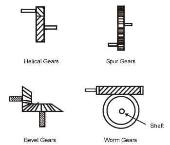
Figure 2-58. Speed reducer gear types
ley or sheave. (3) Bearing friction caused by excessive tension on the pulley (or sheave) causing a high level of drag in the bearings.
Efficiencies of belt transmission systems can be as high as 90-98%. When proper maintenance and belt tension is maintained, these efficiencies can be sustained throughout much of the system’s usable life.
