Nearly all motors exploit the force which is exerted on a current-carrying conductor placed in a magnetic field. The force can be demonstrated by placing a bar magnet near a wire carrying current (Figure 1.1), but anyone trying the experiment will probably be disappointed to discover how feeble the force is, and will doubtless be left wondering how such an unpromising effect can be used to make effective motors.
We will see that in order to make the most of the mechanism, we need to arrange a very strong magnetic field, and make it interact with many conductors, each carrying as much current as possible. We will also see later that although the magnetic field (or ‘excitation’) is essential to the working of the motor, it acts only as a catalyst, and all of the mechanical output power comes from the electrical supply to the conductors on which the force is developed. It will emerge later that in some motors the parts of the machine responsible for the excitation and for the energy converting functions are distinct and self-evident. In the d.c. motor, for example, the excitation is provided either by permanent magnets or by field coils wrapped around clearly deined projecting field poles on the stationary part, while the conductors on which force is developed are on the rotor and supplied with current via sliding brushes. In many motors, however, there is no such clear-cut physical distinction between the ‘excitation’ and the ‘energy-converting’ parts of the machine, and a single stationary winding serves both purposes. Nevertheless, we will find that identifying and separating the excitation and energy-converting functions is always helpful in understanding how motors of all types operate.
Returning to the matter of force on a single conductor, we will first look at what determines the magnitude and direction of the force,

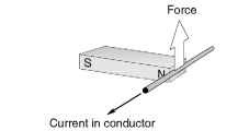
Figure 1.1 Mechanical force produced on a current-carrying wire in a magnetic field
before turning to ways in which the mechanism is exploited to produce rotation. The concept of the magnetic circuit will have to be explored, since this is central to understanding why motors have the shapes they do. A brief introduction to magnetic field, magnetic flux, and flux density is included before that for those who are not familiar with the ideas involved.
Magnetic field and magnetic flux
When a current-carrying conductor is placed in a magnetic field, it experiences a force. Experiment shows that the magnitude of the force depends directly on the current in the wire, and the strength of the magnetic field, and that the force is greatest when the magnetic field is perpendicular to the conductor.
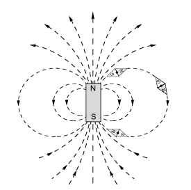
In the set-up shown in Figure 1.1, the source of the magnetic field is a bar magnet, which produces a magnetic field as shown in Figure 1.2.
The notion of a ‘magnetic field’ surrounding a magnet is an abstract idea that helps us to come to grips with the mysterious phenomenon of

Figure 1.2 Magnetic flux lines produced by a permanent magnet
magnetism: it not only provides us with a convenient pictorial way of picturing the directional effects, but it also allows us to quantify the ‘strength’ of the magnetism and hence permits us to predict the various effects produced by it.
The dotted lines in Figure 1.2 are referred to as magnetic flux lines, or simply flux lines. They indicate the direction along which iron filings (or small steel pins) would align themselves when placed in the field of the bar magnet. Steel pins have no initial magnetic field of their own, so there is no reason why one end or the other of the pins should point to a particular pole of the bar magnet.
However, when we put a compass needle (which is itself a permanent magnet) in the field we find that it aligns itself as shown in Figure 1.2. In the upper half of the figure, the S end of the diamond-shaped compass settles closest to the N pole of the magnet, while in the lower half of the figure, the N end of the compass seeks the S of the magnet. This immediately suggests that there is a direction associated with the lines of flux, as shown by the arrows on the flux lines, which conventionally are taken as positively directed from the N to the S pole of the bar magnet.
The sketch in Figure 1.2 might suggest that there is a ‘source’ near the top of the bar magnet, from which flux lines emanate before making their way to a corresponding ‘sink’ at the bottom. However, if we were to look at the flux lines inside the magnet, we would find that they were continuous, with no ‘start’ or ‘finish’. (In Figure 1.2 the internal flux lines have been omitted for the sake of clarity, but a very similar field pattern is produced by a circular coil of wire carrying a d.c. See Figure 1.6 where the continuity of the flux lines is clear.). Magnetic flux lines always form closed paths, as we will see when we look at the ‘magnetic circuit’, and draw a parallel with the electric circuit, in which the current is also a continuous quantity. (There must be a ’cause’ of the magnetic flux, of course, and in a permanent magnet this is usually pictured in terms of atomic-level circulating currents within the magnet material. Fortunately, discussion at this physical level is not necessary for our purpose.)
Magnetic flux density
Along with showing direction, the flux plots also convey information about the intensity of the magnetic ield. To achieve this, we introduce the idea that between every pair of flux lines (and for a given depth into the paper) there is a same ‘quantity’ of magnetic flux. Some people have no difficulty with such a concept, while others find that the notion of quantifying something so abstract represents a serious intellectual challenge. But whether the approach seems obvious or not, there is no denying of the practical utility of quantifying the mysterious stuff we call magnetic flux, and it leads us next to the very important idea of magnetic flux density (B).
When the lux lines are close together, the ‘tube’ of flux is squashed into a smaller space, whereas when the lines are further apart the same tube of lux has more breathing space. The lux density (B) is simply the flux in the ‘tube’ (F) divided by the cross sectional area (A) of the tube, i.e.
![]()
The flux density is a vector quantity, and is therefore often written in bold type: its magnitude is given by equation (1.1), and its direction is that of the prevailing flux lines at each point. Near the top of the magnet in Figure 1.2, for example, the flux density will be large (because the flux is squashed into a small area), and pointing upwards, whereas on the equator and far out from the body of the magnet the flux density will be small and directed downwards.
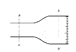
It will be seen later that in order to create high flux densities in motors, the flux spends most of its life inside well-deined ‘magnetic circuits’ made of iron or steel, within which the flux lines spread out uniformly to take full advantage of the available area. In the case shown in Figure 1.3, for example, the cross-sectional area at bb’ is twice that at aa’, but the flux is constant so the flux density at bb’ is half that at aa’.
It remains to specify units for quantity of flux, and flux density. In the SI system, the unit of magnetic flux is the weber (Wb). If one weber of flux is distributed uniformly across an area of 1m2 perpendicular to the flux, the flux density is clearly one weber per square metre

Figure 1.3 Magnetic lux lines inside part of an iron magnetic circuit
(Wb/m2). This was the unit of magnetic flux density until about 40 years ago, when it was decided that one weber per square meter would henceforth be known as one tesla (T), in honour of Nikola Tesla who is generally credited with inventing the induction motor. The widespread use of B (measured in tesla) in the design stage of all types of electromagnetic apparatus means that we are constantly reminded of the importance of tesla; but at the same time one has to acknowledge that the outdated unit did have the advantage of conveying directly what flux density is, i.e. flux divided by area.
In the motor world we are unlikely to encounter more than a few milliwebers of lfux, and a small bar magnet would probably only produce a few microwebers. On the other hand, values of flux density are typically around 1 T in most motors, which is a reflection of the fact that although the quantity of flux is small, it is also spread over a small area.
Force on a conductor
We now return to the production of force on a current-carrying wire placed in a magnetic field, as revealed by the setup shown in Figure 1.1.
The direction of the force is shown in Figure 1.1: it is at right angles to both the current and the magnetic flux density. With the flux density horizontal and to the right, and the current flowing out of the paper, the force is vertically upward. If either the field or the current is reversed, the force acts downwards, and if both are reversed, the force will remain upward.
We find by experiment that if we double either the current or the flux density, we double the force, while doubling both causes the force to increase by a factor of four. But how about quantifying the force? We need to express the force in terms of the product of the current and the magnetic flux density, and this turns out to be very straightforward when we work in SI units.
The force on a wire of length l, carrying a current I and exposed to a uniform magnetic flux density B throughout its length is given by the simple expression
F = BIl (1.2)
where F is in newtons when B is in tesla, I in amperes, and l in metres.
This is a delightfully simple formula, and it may come as a surprise to some readers that there are no constants of proportionality involved in
equation 1.2. The simplicity is not a coincidence, but stems from the fact that the unit of current (the ampere) is actually defined in terms of force.
Strictly, equation 1.2 only applies when the current is perpendicular to the field. If this condition is not met, the force on the conductor will be less; and in the extreme case where the current was in the same direction as the field, the force would fall to zero. However, every sensible motor designer knows that to get the best out of the magnetic field it has to be perpendicular to the conductors, and so it is safe to assume in the subsequent discussion that B and I are always perpendicular. In the remainder of this topic, it will be assumed that the flux density and current are mutually perpendicular, and this is why, although B is a vector quantity (and would usually be denoted by bold type), we can drop the bold notation because the direction is implicit and we are only interested in the magnitude.
The reason for the very low force detected in the experiment with the bar magnet is revealed by equation 1.2. To obtain a high force, we must have a high flux density, and a lot of current. The flux density at the ends of a bar magnet is low, perhaps 0.1 tesla, so a wire carrying 1 amp will experience a force of only 0.1 N/m (approximately 100 gm wt). Since the flux density will be continued to perhaps 1 cm across the end face of the magnet, the total force on the wire will be only 1 gm. This would be barely detectable, and is too low to be of any use in a decent motor. So how is more force obtained?
The first step is to obtain the highest possible flux density. This is achieved by designing a ‘good’ magnetic circuit, and is discussed next. Secondly, as many conductors as possible must be packed in the space where the magnetic field exists, and each conductor must carry as much current as it can without heating up to a dangerous temperature. In this way, impressive forces can be obtained from modestly sized devices, as anyone who has tried to stop an electric drill by grasping the chuck will testify.
