As indicated by the name, this type of control method requires the use of some peripheral device that closes the loop back to the drive. The device that is commonly used is the tachometer, or tach generator, as it is sometimes called. Figure 5-2 indicates a simple closed-loop control scheme.
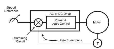
Figure 5-2. Closed-loop control
Closed-loop control is a bit more complex, but yields a great improvement in motor-speed regulation. The key to the success of this scheme is the tachometer (T) or feedback device. A speed reference is given to the AC or DC drive. The actual speed, determined by the tach, is fed back to the drive. Both the speed reference and feedback are combined into the summing circuit. The summing circuit produces an error signal. That error signal is now the speed reference that is sent to the power and logic control, which translates the signal into faster or slower motor speed.
If this happened to be an AC drive configured in torque-control mode, the feedback would be a current feedback instead of speed. If this was a position control, such as a servo controller, the feedback would be a position and use an encoder instead of a tach. The idea of this entire scheme is to have zero error on the output of the summing circuit. If error occurs, it
must be corrected. How fast it is corrected is a function of the logic control in the drive.
The use of proportional integral derivative (PID) is critical to the success of the entire system. The PID controller will be programmed to correct for the error immediately or over a period of time. It will also be programmed as to how much error should be corrected over a period of time. The dynamics and stability of the system is dictated by the responsiveness or sloppi-ness of the feedback loop and control system. As with any type of control system, it is only as good as the weakest link. The remainder of this topic will be devoted to closed-loop components, their accuracy, and how the responsiveness of the system will be affected.
Tachometers
A tachometer generator or tach is an electromechanical device that translates the rotational speed of a shaft to an electrical signal. An analog tach generator is a small generator that produces an output voltage whose magnitude is linearly proportional to shaft speed. An AC tach produces an AC voltage and a DC tach produces a DC voltage. DC tachs produce a negative voltage to indicate reverse rotation as shown in Figure 5-3.
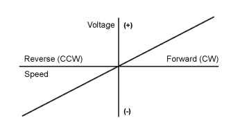
Figure 5-3. DC tach output voltage vs. speed
DC tachs are the most popular type of analog tach, since AC tachs do not indicate direction and are generally less accurate than DC tachs. The output of a DC tach is typically specified in volts per 1000 rpm. The V/1000 rpm voltage constant is the slope of the output voltage versus speed line.
Digital tachs, or pulse tachs as they are sometimes called, produce a series of pulses. The frequency of those pulses is proportional to shaft speed. This can be seen in Figure 5-4.
The output of a digital tach is typically specified in pulses per revolution (PPR). Most pulse tachs are magnetic devices in which pulses are generated by gear teeth passing by a magnetic pickup.
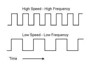
Figure 5-4. Pulse tach output
Encoders
An encoder is an electromechanical device that translates mechanical position and/or velocity into electrical signals. A shaft encoder or rotary encoder translates rotational or angular position and/or velocity into electrical signals.
An incremental encoder provides a signal that indicates position change or incremental position rather than absolute position. In principle, an incremental encoder is essentially the same type of device as a pulse tach, previously discussed. The term encoder usually implies a device with more advanced features and performance. Terms such as incremental encoder, encoder, pulse tach, and digital tachometer are basically used for the same type of device. In industry, they are often used interchangeably.
Optical encoders, on the other hand, are devices that use pulses for rotational signal generation. A light beam is transmitted through transparent stripes or slots in a rotating disk. The photo detector picks up those light beams and converts them into a series of pulses, sometimes called a pulse train. Figure 5-5 shows this process.
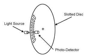
Figure 5-5. Optical encoder characteristics
Optical encoders are the most widely used types of encoder. They are capable of providing very high resolution.
Magnetoresistive encoders have a wheel or disk with numerous small magnetic poles imprinted on the disk surface in alternating north/south pairs. Incremental position is indicated by a sensing element consisting of a combination of resistors that change resistance on the basis of a magnetic field. The sensing element provides input to electronic circuitry, which generate pulses corresponding to each individual imprinted magnetic pole.
An absolute encoder produces a number of binary outputs that can be read as a binary word, which indicate the absolute angular position of the shaft relative to some unique index position. This type of encoder would be used primarily in a system where position feedback would be required (e.g., cut-to-length servo system).
This topic is primarily concerned with motor speed or velocity in drive systems. Therefore, the focus will be on the incremental encoder or pulse tach, rather than on absolute encoders devices.
Encoder Characteristic
The following paragraphs explain several encoder features that provide functions and performance that go beyond simply indicating shaft speed.
An encoder with a single output cannot indicate direction of rotation. Quadrature outputs are two outputs with a 90° phase displacement, as shown in Figure 5-6.
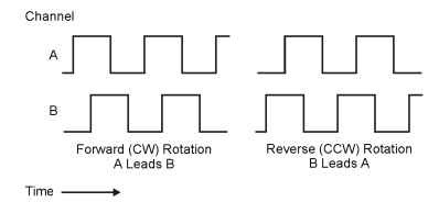
Figure 5-6. Quadrature outputs of a pulse tach (encoder)
As shown in Figure 5-6, quadrature outputs can be used to determine direction of rotation by detecting which of the two output signals is leading. The low-to-high transitions of the leading signal occur before the low-to-high transitions of the lagging signal.
Incremental encoders can be used to indicate when the shaft is in one particular “index” position. This is done by using an index pulse or marker pulse that occurs only once per revolution at the index position. Figure 5-7
shows this procedure. The width and phase relationship of the index pulse may vary among encoder models.
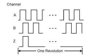
Figure 5-7. Encoder marker pulses of index positions
Figure 5-8 indicates complementary or differential outputs. Complementary outputs are pairs of outputs that are configured in such a way that one output (A) is high whenever its complement (A) is low.
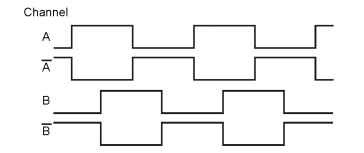
Figure 5-8. Complementary or differential outputs
A and A represent the signal voltages with respect to circuit common. The voltage between the A output and the A output is the voltage difference, or differential, between the A and A-voltages. An encoder output signal that does not include the complementary A and B signals is called a single-ended output.
Differential signals have better noise immunity than single-ended signals. Figure 5-9 indicates a differential line driver and receiver connected by a twisted pair of shielded wires—a transmission line.

Figure 5-9. Differential line driver and receiver diagram
The use of a differential line driver and receiver protects against common mode noise between the transmitting and receiving locations. The use of a shielded, twisted-pair transmission line protects the signal from electromagnetic fields that might interfere with signal transmission.
The resolution of an encoder is determined by the number of pulses per revolution of the encoder shaft. The resolution determines the smallest amount of shaft rotation that the encoder is able to indicate. If an encoder generates 1024 pulses per revolution, it can indicate a movement of 1/ 1024 of a revolution or 0.35 degrees of rotation. The effective resolution of an encoder can be improved by using pulse multiplication. This procedure is shown in Figure 5-10.
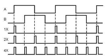
Figure 5-10. Encoder wiring diagram
The A and B signals shown in Figure 5-10 are the outputs of a quadrature encoder. The 1X signal is a series of narrow pulses corresponding to the low-to-high transitions of the A signal. These pulses are typically generated by the device that receives or uses the encoder signal.
The resolution of the 1X signal is equal to the encoder PPR. The 2X signal contains pulses corresponding to both the low-to-high transitions and the high-to-low transitions of the A signal. The resolution of the 2X signal is twice the encoder PPR. The 4X signal contains pulses corresponding to the low-to-high and high-to-low transitions of both the A and the B signals. The effective resolution of the 4X signal is four times the encoder PPR.
To correctly apply encoders, the specifications of the encoder must be determined. Then the applications specifics can be matched to the encoder that would best meet the requirements. At this point, a review of typical encoder specifications is in order.
Encoder Specifications
The most basic encoder specification is the resolution or number of pulses per revolution of the encoder shaft. In general, using the highest possible pulses per revolution allows the best possible drive performance. High PPR allows speed to be measured more accurately and sampled more fre-
quently. The pulse frequency is determined by the encoder-operating speed and the resolution according to the following formula:

The following example illustrates the pulse-frequency calculation for a 2048 PPR encoder operating at 1800 rpm. Note that the pulse frequency unit of measurement, hertz, is equivalent to pulses per second. The minute and revolution units cancel, leaving pulses-per-second or hertz as the units of measurement.

The encoder PPR must be selected so that the pulse frequency is high enough to allow the required performance at the minimum operating speed. At the maximum operating speed, the pulse frequency must not exceed the maximum output frequency capability of the encoder. It also must not exceed the maximum input frequency capability of the circuitry that receives the signal.
Some drives can be adjusted to accept any PPR value within a specified range. Other drives accept only specific PPR values, such as 1024 PPR or 2048 PPR. The accuracy of an encoder is the maximum percentage variation between the actual positions of the pulse edges or transitions and the theoretical correct positions. The encoder accuracy is not the only factor that determines the speed-measurement accuracy. Speed-measurement accuracy is influenced by the encoder timing and counting accuracy. It is also influenced by the mechanical backlash in the coupling to the machine.
The measurement method may improve upon the encoder accuracy by averaging a number of pulses in each measurement. When speed is averaged over an extended period of time, the measurement accuracy will be determined entirely by the timing and counting accuracy.
The basic specification for the output signals indicates whether the encoder has a single output or quadrature output and whether or not a zero marker is provided. If complementary output signals are provided, the encoder specification may identify the IC-type number for the line driver. The output voltage and current ratings should also be specified. Single-ended outputs are often open collector, current sinking outputs. Most encoders provide square-wave outputs (50% duty cycle), but some models may be available with a fixed-pulse width.
Output specifications must be checked for compatibility with the circuitry that will receive the signal. Encoders require an external power source. The most common requirements are 12 and 24 VDC. Encoders are also available for operation at 5 VDC. However, these encoders are not recommended for installations requiring a long cable distance between the encoder and the drive.
Most encoders require a regulated input supply voltage and provide an output at the same voltage level as the input voltage. If the encoder has its own voltage regulator, its output signal level will be considerably lower than the input supply voltage. If the drive is designed to provide a regulated encoder supply voltage, it may not accept an encoder signal at a voltage level that is significantly below the supply voltage.
Before installation, the user should verify that the output voltage of the encoder is compatible with the input voltage range of the drive’s encoder input. In addition, all encoders have minimum and maximum operating temperature ratings. If the encoder is subjected to temperatures outside the specified limits, it may not operate correctly and can ultimately be damaged. A possible source of encoder damage is heat. Heat is very likely to be conducted to the encoder housing through the mounting structure from motor or machine. An encoder should be selected with an operating temperature rating that is suitable for the location and mounting method.
A variety of mechanical specifications define the type of encoder housing available and the type of mounting arrangement possible. Encoders are available with various degrees of protection from moisture and environmental contaminants. The degree of protection is determined by the encoder housing type and material, the shaft material, the type of shaft seal, etc. Explosion-proof models are available for use in areas where fire or explosion hazards may exist because of flammable gases or vapors. Various bearing ratings are available to accommodate a wide range of radial and axial loads that might be subjected to the shaft of the encoder.
There will also be a maximum operating speed determined by the mechanical construction of the encoder. For each PPR rating, there will be a maximum speed corresponding to the encoder’s maximum output frequency capability as described in a previous paragraph. The encoder manufacturer’s installation and alignment procedures must always be carefully followed to ensure reliable operation.
Once the encoder is properly installed, it must be wired to the specifications of both the encoder and drive manufacturer. Careful attention to wiring is essential to ensure that a drive with encoder feedback performs properly. The following recommendations cover the most common requirements.
Each encoder output channel and the power supply should be connected using an individually shielded twisted pair of wires. Encoder wiring and a connection scheme are shown in Figure 5-11.
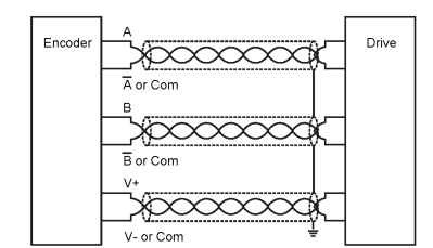
Figure 5-11. Encoder wiring diagram
Three individual cables or a three-pair cable can be used. If a three-pair cable is used, be sure that each pair of wires is individually shielded. The shields are to be grounded as recommended by the drive instruction material. Shielded cable is grounded at only one point to prevent ground loops or circulating currents through the shield conductor. The best ground location is usually at the drive. The encoder cable must be run in a steel conduit. Cables from more than one encoder can be run in the same conduit, but the conduit cannot carry power wiring.
Encoder cable should be a low-capacitance type of cable, designed for high-speed digital signals such as RS-422/485 serial communications signals.
Since the relationship between encoder shaft rotation and quadrature signal phasing is not standardized, this relationship can vary among encoder models. The instruction material furnished with the encoder is the best source of determining the encoder phasing. Phasing corresponds to the selected motor direction. If the drive does not operate properly upon initial startup, encoder phasing could be a suspect. It may be necessary to determine proper phasing by trial and error.
Note: Today’s microprocessor-based adjustable-speed drives are designed for use with incremental encoders rather than analog tachometer generators. Although some models may accept a feedback signal from a DC tach, the best performance is obtained by using an encoder. Analog tachometer generators have better EMI immunity compared with encoders. However, with the use of differential signals and careful attention to wiring, EMI immunity of an encoder can be equal or better than that of an analog tach.
If an analog tach is used, it is necessary to determine what range of signals are compatible with the drive circuitry that it will be connected to. The circuit must be designed for either a DC or AC tach. The maximum input voltage and tach-generating voltage at maximum speed are factors to consider before purchasing a tach. Using a tach with the maximum compati-
ble volts per 1000 rpm will provide the best performance over a wide speed range.
Resolvers
A resolver is a “position” transducer, with characteristics that resemble a small motor. This type of feedback device would be used mainly with servo motor applications where precise feedback of rotor position is critical to system accuracy. For example, in cut-to-length applications, linear position of a sliding table or cutting arm would be a function of the position of the rotor. Figure 5-12 shows a diagram of a resolver.

Figure 5-12. Resolver diagram
A resolver is very similar to an AC induction motor. A resolver contains a single winding rotor that rotates inside fixed coils of wire, called stators. A reference voltage is typically applied to the rotor winding. This rotating winding has a magnetic field that induces a voltage in the stator windings, which produce an analog output. This analog output is proportional to shaft (rotor) rotation.
Basically, the resolver is a rotating transformer. The rotating primary (rotor) induces a voltage in the fixed winding secondaries (stator windings). The analog output is what is fed back to the drive as an actual speed signal, or what would be considered a position signal.
Because there are no electronics involved with resolvers, they are better suited for dirty environments than encoders. Also, the resolver is a device that is an absolute measuring instrument. It can retain its exact location during a power outage. Typically the resolver can transmit information over distances up to 1000 feet with little effect from electrical noise. The resolution of some resolvers can be rated as high as 16,384 counts (14 bit or 214).
