The aims of this topic are:
1. To give examples of the use of the Arc, Ellipse, Polygon, Rectangle, tools from the Home/Draw panel.
2. To give examples of the uses of the Polyline Edit (pedit) tool.
3. To introduce the Object Snaps (osnap) and their uses.
4. To introduce the Dynamic Input (DYN) system and its uses.
Introduction
The majority of tools in AutoCAD 2011 can be called into use by any one of the following six methods:
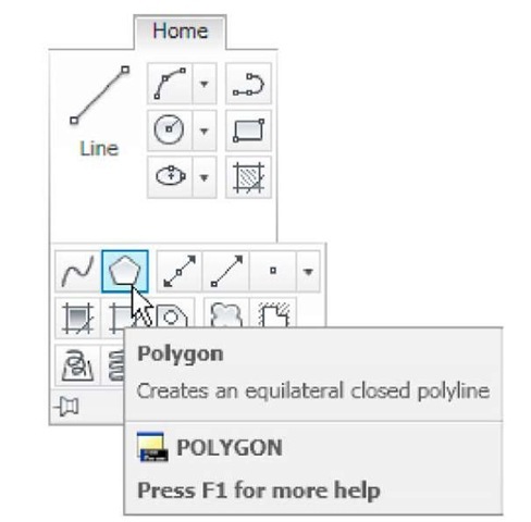
1. By clicking on the tool’s icon in the appropriate panel. Fig. 3.1 shows the Polygon tool called from the Home/Draw panel.
Fig. 3.1 The Polygon tool and its tooltip selected from the Home/Draw panel
Fig. 3.2 The tool icons in the Draw toolbar
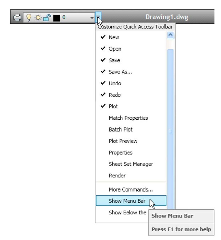
2. By clicking on a tool icon in a drop-down menu. Fig. 3.2 shows the tool names and icons displayed in the Draw drop-down menu. It is necessary to first bring the menu bar to screen with a click on Show Menu Bar in the left-click menu of the Quick Access toolbar (Fig. 3.3) if the menu bar is not already on screen.
3. By entering an abbreviation for the tool name at the command line. For example, the abbreviation for the Line tool is l, for the Polyline tool it is pl and for the Circle tool it is c.
4. By entering the full name of the tool at the command line.
5. By making use of the Dynamic Input method of construction.
6. If working in the AutoCAD Classic workspace by selection of tools from toolbars.
In practice operators constructing drawings in AutoCAD 2011 may well use a combination of these six methods.
Fig. 3.3 Selecting Show Menu Bar from the left-click menu in the Quick Access toolbar
The Arc tool
In AutoCAD 2011, arcs can be constructed using any three of the following characteristics of an arc – its Start point, a point on the arc (Second point), its Center, its End, its Radius, the Length of the arc, the Direction in which the arc is to be constructed, the Angle between lines of the arc.
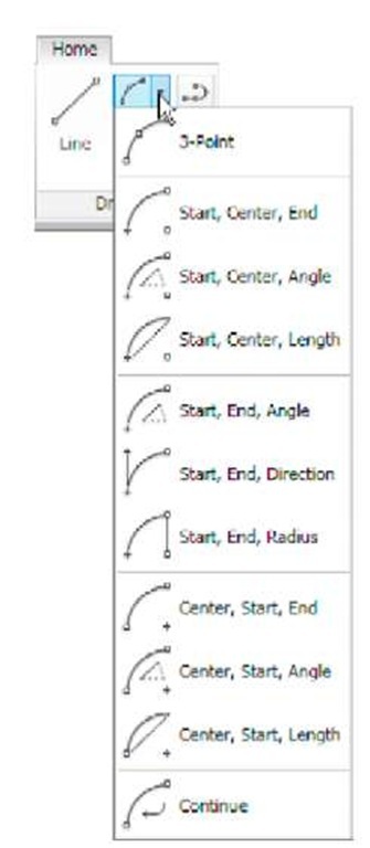
These characteristics are shown in the menu appearing with a click on the arrow to the right of the Arc tool icon in the Home/Draw panel (Fig. 3.4).
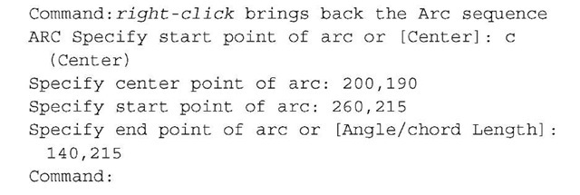
To call the Arc tool click on the fly out of its tool icon in the Home/Draw panel, click on Arc in the Draw drop-down menu or enter a or arc at the command line. In the following examples, initials of prompts will be shown instead of selection from the menu as shown in Fig. 3.5.
Fig. 3.4 The Arc tool fly out in the Home/ Draw panel
Fig. 3.5 Examples – Arc tool
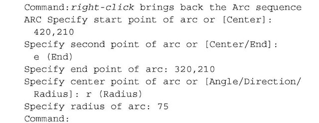
First example – Arc tool (Fig. 3.5)
Left-click the Arc tool icon. The command line shows:
Second example – Arc tool (Fig. 3.5)
Third example – Arc tool (Fig. 3.5)
The Ellipse tool
Ellipses can be regarded as what is seen when a circle is viewed from directly in front of the circle and the circle rotated through an angle about its horizontal diameter. Ellipses are measured in terms of two axes – a major axis and a minor axis, the major axis being the diameter of the circle and the minor axis being the height of the ellipse after the circle has been rotated through an angle (Fig. 3.6).
Fig. 3.6 An ellipse can be regarded as viewing a rotated circle
To call the Ellipse tool, click on its tool icon in the Home/Draw panel (Fig. 3.7), click its name in the Draw drop-down menu or enter a or arc at the command line.
Fig. 3.7 The Ellipse tool icon fly out in the Home/Draw panel
First example – Ellipse (Fig. 3.8)
Left-click the Ellipse tool icon. The command line shows:
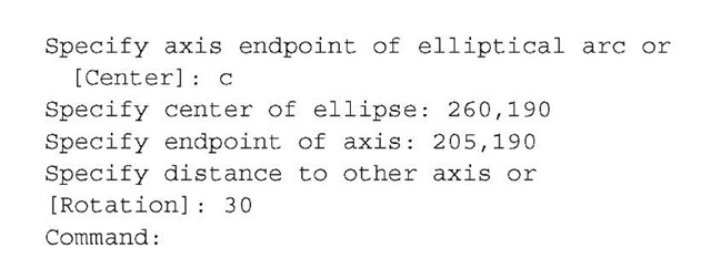
Second example – Ellipse (Fig. 3.8)
In this second example, the coordinates of the centre of the ellipse (the point where the two axes intersect) are entered, followed by entering coordinates for the end of the major axis, followed by entering the units for the end of the minor axis.
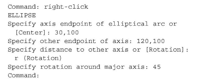
Third example – Ellipse (Fig. 3.8)
In this third example, after setting the positions of the ends of the major axis, the angle of rotation of the circle from which an ellipse can be obtained is entered (Fig. 3.8).
Fig. 3.8 Examples – Ellipse
