The AutoCAD coordinate system
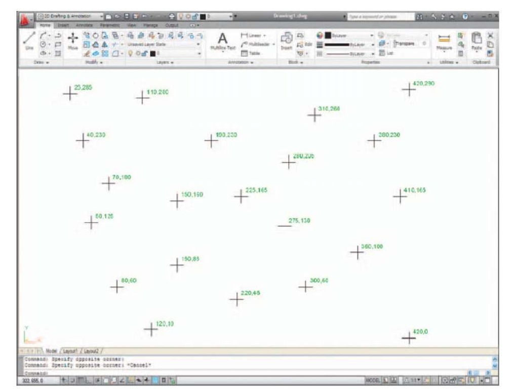
In the AutoCAD 2D coordinate system, units are measured horizontally in terms of X and vertically in terms of Y. A 2D point in the AutoCAD drawing area can be determined in terms of X,Y (in this topic referred to as x,y). x,y = 0,0 is the origin of the system. The coordinate point x,y = 100,50 is 100 units to the right of the origin and 50 units above the origin. The point x,y = -100, -50 is 100 units to the left of the origin and 50 points below the origin. Fig. 1.20 shows some 2D coordinate points in the AutoCAD window.
Fig. 1.20 The 2D coordinate points in the AutoCAD coordinate system
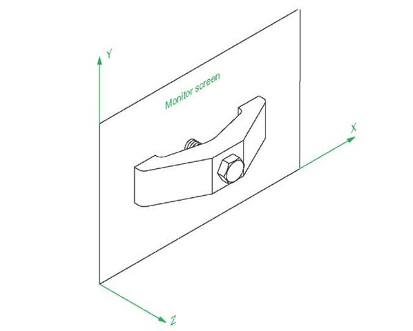
3D coordinates include a third coordinate (Z), in which positive Z units are towards the operator as if coming out of the monitor screen and negative Z units going away from the operator as if towards the interior of the screen. 3D coordinates are stated in terms of x,y,z. x,y,z = 100,50,50 is 100 units to the right of the origin, 50 units above the origin and 50 units towards the operator. A 3D model drawing as if resting on the surface of a monitor is shown in Fig. 1.21.
Fig. 1.21 A 3D model drawing showing the X, Y and Z coordinate directions
Drawing templates
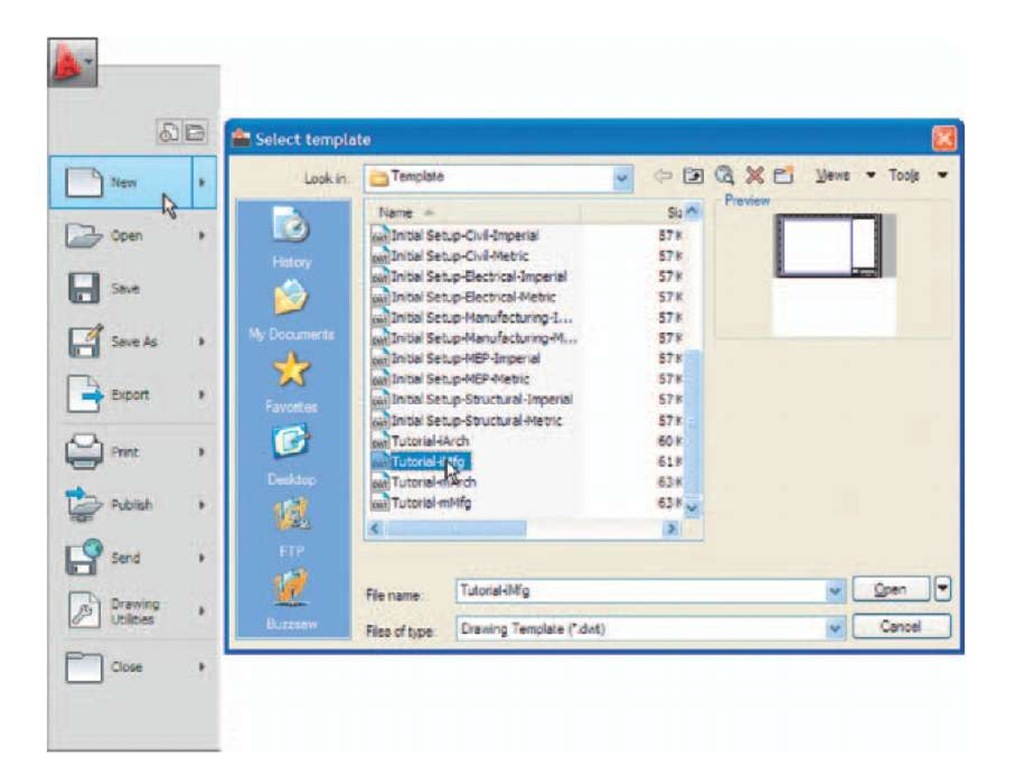
Drawing templates are files with an extension .dwt. Templates are files which have been saved with predetermined settings – such as Grid spacing and Snap spacing. Templates can be opened from the Select template dialog (Fig. 1.22) called by clicking the New. icon in the Quick Access toolbar. An example of a template file being opened is shown in Fig. 1.22. In this example the template will be opened in Paper Space and is complete with a title block and borders.
Fig. 1.22 A template selected from the Select template dialog
When AutoCAD 2011 is used in European countries and opened, the acadiso.dwt template is the one most likely to appear on screen. In this part (Part 1 – 2D Design) of this topic drawings will usually be constructed in an adaptation of the acadiso.dwt template. To adapt this template:
1. In the command palette enter (type) grid followed by a right-click (or pressing the Enter key). Then enter 10 in response to the prompt which appears, followed by a right-click (Fig. 1.23).
Fig. 1.23 Setting Grids to 10
2. In the command palette enter snap followed by right-click. Then enter 5 followed by a right-click (Fig. 1.24).
Fig. 1.24 Setting Snapto5
3. In the command palette enter limits, followed by a right-click. Right-click again. Then enter 420, 297 and right-click (Fig. 1.25).
Fig. 1.25 Setting Limits to 420,297
4. In the command palette enter zoom and right-click. Then in response to the line of prompts which appears enter a (for All) and right-click (Fig. 1.26).
Fig. 1.26 Zooming to All
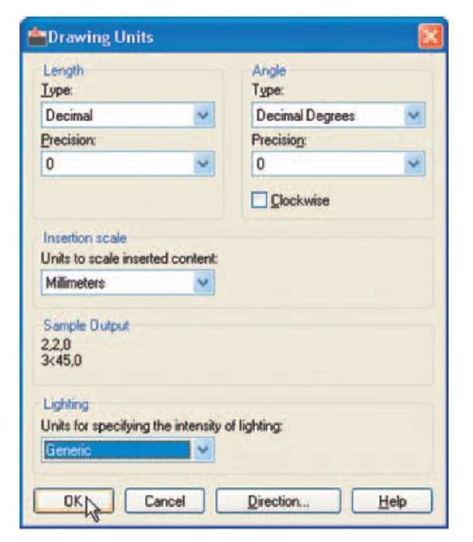
5. In the command palette enter units and right-click. The Drawing Units dialog appears (Fig. 1.27). In the Precision popup list of the Length area of the dialog, click on 0 and then click the OK button. Note the change in the coordinate units showing in the status bar.
Fig. 1.27 Setting Units to 0
6. Click the Save icon in the Quick Access toolbar (Fig. 1.28). The Save Drawing As dialog appears. In the Files of type popup list select AutoCAD Drawing Template (*.dwt). The templates already in AutoCAD are displayed in the dialog. Click on acadiso.dwt, followed by another click on the Save button.
Fig. 1.28 Click Save
Notes
1. Now when AutoCAD is opened the template saved as acadiso.dwt automatically loads with Grid set to 10, Snap set to 5, Limits set to 420,297 (size of an A3 sheet in millimetres) and with the drawing area zoomed to these limits, with Units set to 0.
2. However, if there are multiple users by the computer, it is advisable to save your template to another file name, e.g. my_template.dwt.
3. Other features will be added to the template in future topics.
Methods of showing entries in the command palette
Throughout the topic, a tool is "called" usually by a click on a tool icon in a panel – in this example entering zoom at the command line and the following appears in the command palette:
Note
In later examples this may be shortened to:
Notes
1. In the above enter means type the given letter, word or words at the Command: prompt.
2. Right-click means press the Return (right) button of the mouse or press the Return key of the keyboard.
Tools and tool icons
In AutoCAD 2011, tools are shown as names and icons in panels or in drop-down menus. When the cursor is placed over a tool icon a description shows with the name of the tool as shown and an explanation in diagram form as in the example given in Fig. 1.7.
If a small outward-facing arrow is included at the right-hand side of a tool icon, when the cursor is placed over the icon and the pick button of the mouse depressed and held, a flyout appears which includes other features. An example is given in Fig. 1.8.


