Saving drawings
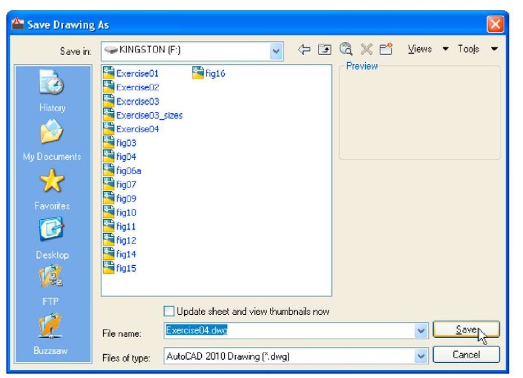
Before going further it is as well to know how to save the drawings constructed when answering examples and exercises in this topic. When a drawing has been constructed, left-click on Save As in the menu appearing with a left-click on the AutoCAD icon at the top left-hand corner of the window (Fig. 3.9). The Save Drawing As dialog appears (Fig. 3.10).
Fig. 3.9 Selecting Save As from the Quick Access menu
Fig. 3.10 The Save Drawing As dialog
Unless you are the only person using the computer on which the drawing has been constructed, it is best to save work to a USB memory stick or other form of temporary saving device. To save a drawing to a USB memory stick:
1. Place a memory stick in a USB drive.
2. In the Save in: field of the dialog, click the arrow to the right of the field and from the popup list select KINGSTON [F:] (the name of my USB drive and stick).
3. In the File name: field type a name. The file name extension .dwg does not need to be typed – it will be added to the file name.
4. Left-click the Save button of the dialog. The drawing will be saved with the file name extension .dwg – the AutoCAD file name extension (Fig. 3.10).
Snap
In previous topics, several methods of constructing accurate drawings have been described – using Snap, absolute coordinate entry, relative coordinate entry and tracking. Other methods of ensuring accuracy between parts of constructions are by making use of Object Snaps (Osnaps).
Snap Mode, Grid Display and Object Snaps can be toggled on/off from the buttons in the status bar or by pressing the keys, F9 (Snap Mode), F7 (Grid Display) and F3 (Object Snap).
Object Snaps (Osnaps)
Object Snaps allow objects to be added to a drawing at precise positions in relation to other objects already on screen. With Object Snaps, objects can be added to the end points, midpoints, to intersections of objects, to centres and/or quadrants of circles and so on. Object Snaps also override snap points even when snap is set on.
To set Object Snaps – at the command line:
And the Drafting Settings dialog appears (Fig. 3.11). Click the Object Snap tab in the upper part of the dialog and click the check boxes to the right of the Object Snap names to set them on (or off in on).
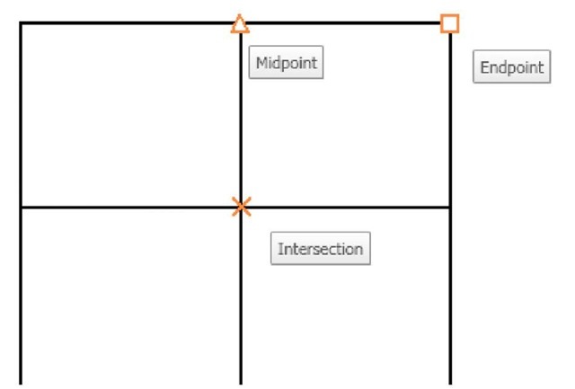
When Object Snaps are set ON, as outlines are constructed using Object Snap icons and their tooltips appear as indicated in Fig. 3.12.
Fig. 3.11 The Drafting Settings dialog with some of the Object Snaps set on
Fig. 3.12 Three Object Snap icons and their tooltips
It is sometimes advisable not to have Object Snaps set on in the Drafting Settings dialog, but to set Object Snap off and use Object Snap abbreviations at the command line when using tools. The following examples show the use of some of these abbreviations. Object Snaps can be toggled on/off by pressing the F3 key of the keyboard.
First example – Object Snap (Fig. 3.13)
Call the Polyline tool:
The result is shown in Fig. 3.13. In this illustration the Object Snap tooltips are shown as they appear when each object is added to the outline.
Second example – Object Snap abbreviations (Fig. 3.14)
Call the Circle tool:
Fig. 3.13 First example – Osnaps
Notes
With Object Snaps off, the following abbreviations can be used:
end – endpoint; mid – midpoint; int – intersection; cen – centre; qua – quadrant;
nea – nearest;
ext – extension.(Fig. 3.14)
Fig. 3.14 Second example – Osnaps
Dynamic Input (DYN)
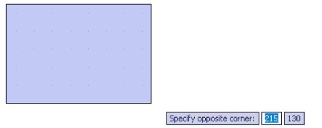
When Dynamic Input is set on by either pressing the F12 key or with a click on the Dynamic Input button in the status bar, dimensions, coordinate positions and commands appear as tips when no tool is in action (Fig. 3.15).
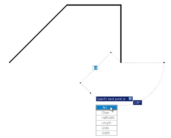
With a tool in action, as the cursor hairs are moved in response to movement of the mouse, Dynamic Input tips showing the coordinate figures for the point of the cursor hairs will show (Fig. 3.16), together with other details.
Fig. 3.15 The DYN tips appearing when no tool is in action and the cursor is moved
To see the drop-down menu giving the prompts available with Dynamic Input press the down key of the keyboard and click the prompt to be used. Fig. 3.16 shows the Arc prompt as being the next to be used when the Polyline tool is in use.
Fig. 3.16 Coordinate tips when DYN is in action


