Introduction
Our early interest in development of a surgical navigation system arose from our background in computer-assisted frame stereotaxy [1,2] and the early development of "frameless stereotaxy” devices by Roberts et al. [3,4] and Watanabee et al. [5]. Roberts’ group had devised a stereotactic surgical microscope using a sonic three-dimensional digitizer to locate the optical axis and focal point of the microscope in space. Because of the great uncertainty of each acquisition of the sonic digitizer, a stationary platform, such as the microscope, allowed for multiple acquisitions that would average out the "noise" and lead to acceptable accuracy. On the other hand, the Watanabees used a mechanical arm with analogue position sensors in the joints as the input device. This allowed for hand-held navigation, but constrained the user’s freedom by the mechanical linkage.
Don Kormos, Charles Steiner, and I set out to create a hand-held "wand" that did not require linkage but used sonic digitization as used by Roberts. Through painstaking experiments, we discerned that by placing the detectors (microphones) within a meter of the emitters (spark gaps) on the wand and using an internal speed of sound reference (to compensate for temperature, humidity, etc.) we had a flexible, highly accurate digitizer suitable for use in the operating room [6-8]. Teaming up with Picker International (Highland Heights, Ohio), we developed the system into a Food and Drug Administration (FDA)-approved product (ViewPoint™) that was the first in North America to introduce wand-oriented views (i.e., orthogonal planes oriented to the axis of the pointing device), a visual method of target and trajectory guidance [9], and FDA approval for brain biopsy [10]. Ian Kalfas made important contributions that led to the system also being approved for spinal navigation [11], with or without spinal tracking. The system has proved versatile [12,13], cost effective [14], and useful for surgery of intra-axial tumors [15-20], meningiomas [19,21-23], sellar tumors [24], neuroendoscopy [25,26], brain biopsy [27], and related procedures [28].
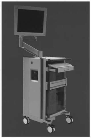
Ultimately, the sonic digitizer was replaced by an active/passive infrared wand detected by a dual CCD camera; multiple and universal tools were developed; Picker International became Marconi Medical Systems, Inc. (Highland Heights, Ohio); and ViewPoint was renamed "Voyager." Today the Voyager system (Fig. 1) retains the ease of use that was the hallmark of the ViewPoint system but extends its versatility with multimodality navigation (i.e., image fusion), a more versatile display, and a more sophisticated platform.
System Setup
Voyager is composed of the dual CCD camera stand, the equipment rack with integrated flat panel light-emitting diode (LED) display and an (optional) outboard flat panel liquid crystal display (LCD) [7]. The camera stand houses a dual CCD infrared camera (Northern Digital Inc.) along with infrared emitters that allow for use of passive tools. The cameras may be oriented either horizontally or vertically, the latter allowing for a narrower line-of-sight corridor between the pointing devices and camera. Unlike some surgical navigation systems, Voyager allows for the camera to be plugged into the equipment rack after the computer has been "booted" up, without damaging the camera. The camera is currently filtered to allow it to operate in the presence of most commercial operating room and head lights.
The new equipment rack houses the system computer, uninterruptable power supply, camera adapter, keyboard, mouse, and the main flat panel display. System connections are also made here, including ethernet, camera, foot pedals, and cabling for active LEDs. Atop the rack is an extension arm that allows the display to be positioned close to the surgeon while keeping the rack out of the way. A working display on the rack allows the sophisticated software functions (beyond those performed with the foot pedals) to be operated by someone else without moving the surgeon’s display. As always, safety is paramount and the uninterruptable power supply serves to electrically isolate the system and maintain function, even in the event of external power loss. Even if the computer loses power, however, all registration information is retained and the surgery may proceed forward seamlessly.
Figure 1 Voyager system composed of dual CCD camera, equipment rack with extendable flat panel liquid crystal display (LCD), and outboard flat panel LCD display.
System Use
Image Loading
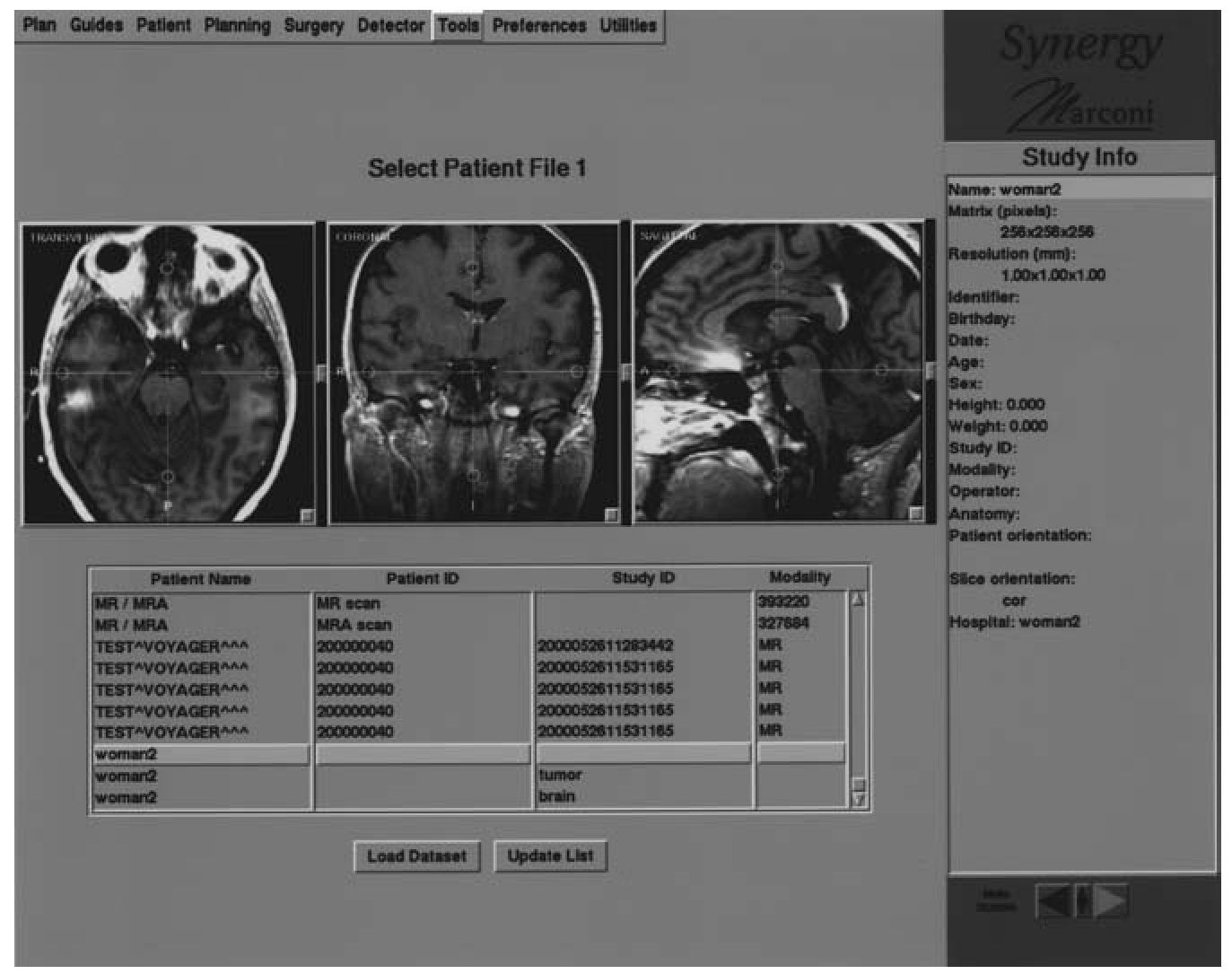
The initial step using the Voyager system is to load the patient’s images. This is typically done over an ethernet system loading DICOM-compatible image files. The operator chooses whether one or more image sets is to be loaded and identifies them; the images are then imported (Fig. 2). If the images were previously loaded into Voyager, the patient file may be loaded instead of the raw image data.
Multimodality Correlation (Fusion)
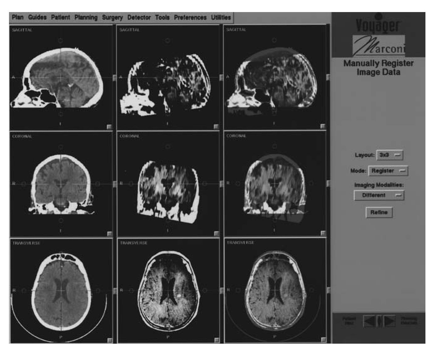
When one or more image datasets are loaded, they must be correlated. Voyager allows for manual or automated fusion of data sets. The author prefers manual fusion, as it is fast, accurate, and totally under his control. Briefly, a 3 X 3 (or, optionally, a 2 X 2) workspace is presented in which one column represents image set 1; the second, image set 2; and the third is where the fusion is performed and displayed (Fig. 3). A useful technique is to assign the second dataset a color profile while the first set is left as a grayscale. Images may be magnified (”zoom”) to facilitate the process. Images are then translated to roughly center the ventricular system, then rotated to align the ventricles and brainstem. This process is performed iteratively until the desired result is obtained, usually in a few minutes or less. If the area of interest is remote from the ventricles, the surgeon may focus on that area, to locally refine the fusion, but this is rarely necessary.
Figure 2 Image loading display of Voyager system. More than one type of image set may be imported for navigation.
Figure 3 Multimodality correlation screen (fusion). Left column represents dataset 1, middle is dataset 2, and right is where fusion is performed and visualized.
Imaging and Registration
Voyager uses paired points to provide registration. For cranial use, these may be anatomical landmarks, applied scalp fiducials, or implanted ”Ac-custar” skull fiducials. The latter routinely results in submillimetric registration accuracy. Fiducials and image acquisition may be performed from the day of surgery to weeks earlier. Fiducials are typically placed in a stereotypical array that are widely spaced about the patient’s head, as this minimizes navigation error, not just registration error.
Thin slice (1 -2 mm) computed tomogram (CT) or volume acquisition magnetic resonance imaging (MRI) (e.g., Siemens MPR) are preferred but may be augmented with other image data using the fusion process (above), such as nuclear medicine, other magnetic resonance imaging (MRI), MR angiography (MRA), magnetic resonance ventilation (MRV), fMRI, and medical radiation sciences (MRS). As such, if fiducials are used, only one of the image methods need visualize the fiducials. Imaging from spinal surgery typically is performed using thin slice CT.
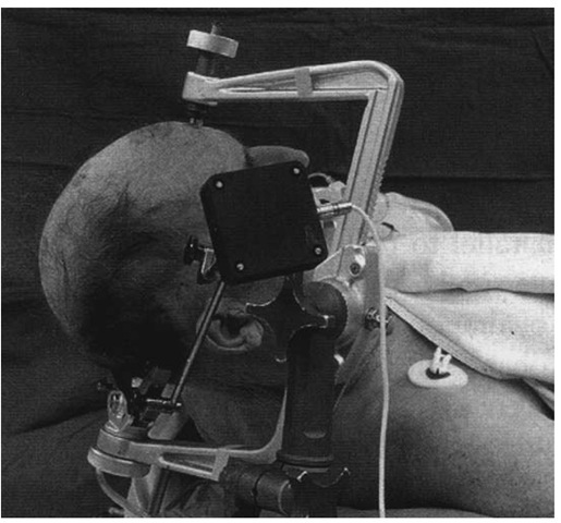
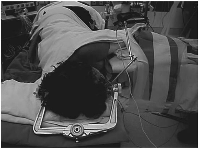
Cranial surgery using Voyager should be performed using head tracking as provided by a dynamic reference frame (DRF). This allows the patient’s head to be followed if it moves with respect to the camera, or vice versa. We routinely affix the DRF to a Mayfield head clamp that has been secured to the patient’s head in such a way as to avoid displacing scalp fiducials. Ordinarily, the Mayfield is then secured to the operating room table to provide good surgical access while providing adequate cranial venous drainage and spinal alignment. The DRF may be secured to the body of the Mayfield or, uniquely, to a modified ”C-arm” of the device, as the latter is least likely to move with respect to the patient’s head during a case (Fig. 4). The DRF is positioned such that it is out of the surgeon’s way, maintains good line-of-sight with the camera, and will not be subject to undue traction by draping. Awake craniotomy is performed using the same setup, except that the Mayfield is applied using local anesthesia (Fig. 5), and the Mayfield clamp is NOT secured to the table, thereby allowing the limited freedom to move while maintaining accurate tracking using the DRF (Fig. 5). An unusual feature of Voyager is that it allows spinal surgery to be performed with or without use of a spinal DRF.
Figure 4 Optional fixation of dynamic reference display (DRF) to modified C-arm of Mayfield head fixation device minimizes fidelity of head tracking, as head may pivot with respect to main part of Mayfield device.
After creation of a registration set, the anatomical or scalp fiducials are defined. This is facilitated by visualizing the three-dimensional surface representation of the head and clicking on its surface near the point of interest. The actual location of the point is refined through use of the triplanar display and stored. The process is repeated for the remaining reference points. Each point is then touched with one of the wands [active infrared (IRED) or passive]. Fiducials that cannot be accessed or have been displaced can be inactivated. Spinal registration uses segmental (i.e., each vertebra) anatomical fiducials in a similar process, often using the tips of the spinal and transverse processes. Multiple registration sets may be created, including intraoperative sets that may be used for re-registration.
Registration error is typically less than 2 mm or 3 mm and submilli-metric when using the Accustar fiducials. Larger errors may be reduced by using the ”Pin Point” function that tracks registration error as the user adjusts the position of the wand on the fiducial. Registration should always be checked by activating the system and ensuring that fiducials and anatomy are accurately localized.
Figure 5 Setup for awake craniotomy. Mayfield clamp is not secured to the table allowing some head movement during surgery while tracking is maintained.
