Target and Trajectory Guidance
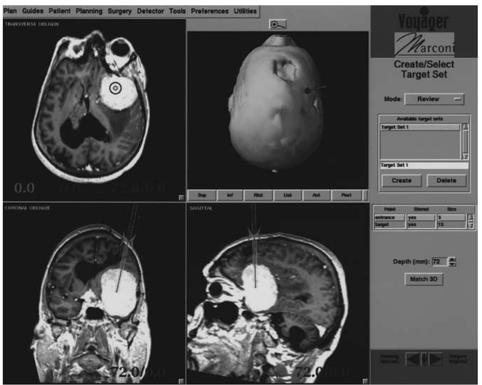
Voyager (then ViewPoint) was the first of the commercial surgical navigation systems to incorporate an intuitive, graphical means of target and trajectory guidance [9]. This was facilitated by its ability to display images oriented to the pointing device (e.g., wand). A target (with optional entry) point is defined by clicking on a point in the image and storing it as either a target or trajectory. If an entry point is also selected, the trajectory may then be previewed with two views, one showing the path of trajectory as it passes through the tissue and the other showing a plane perpendicular to the axis of the trajectory (Fig. 6). The depth of this plane is user selectable.
The method by which this technology is used to guide the surgeon has been previously described [9]. Briefly, when using target guidance alone, the one plane that is perpendicular to the pointing device (e.g., wand) and that also contains the target point (presented as a colored circle) is displayed. The projection of the wand is displayed as a different colored circle. One need only adjust the direction of the wand such that the two circles are concentric to be on target. The three-dimensional error (minimum distance between the trajectory and the target) is continuously presented. The course of the trajectory may be visualized on the two displayed planes that contain the wand. When a trajectory has been created, the perpendicular plane also shows the projection of the entry point, but more importantly, the wand-oriented displays and the three-dimensional display show the planned trajectory as well as actual axis of the wand. A few maneuvers are all that are usually necessary to make the wand align with the planned trajectory.
Intraoperative Use
The patient is draped in a conventional manner except that the DRF must have line of sight with the camera. We usually perforate the drape and apply a sterile, clear plastic bag over it. Care must be taken that the draping does not apply traction to the DRF during the case, even when the drapes become laden with fluid and blood, and that the DRF will not be struck by equipment or an assistant. The author prefers the scrub table to be placed to his right, mediated by a draped Mayo stand, rather than with an overhead table. This allows for placement of the camera at the patient’s feet and out of the way of other equipment.
Figure 6 Display for target and trajectory guidance. Top left screen is plane containing target point and perpendicular to pointing device. Bottom row shows planes containing pointing device and projection of planned trajectory. Top right shows surface representation of the head with planned and actual trajectory. This system facilitates brain biopsy and related procedures.
If active wands are used, they are coupled to the navigation system. Passive wands are identified and then may be used. Universal adapters may be applied to instruments, (drills, probes, etc.), calibrated, then used. Many operating microscopes are used, but image injection is not supported.
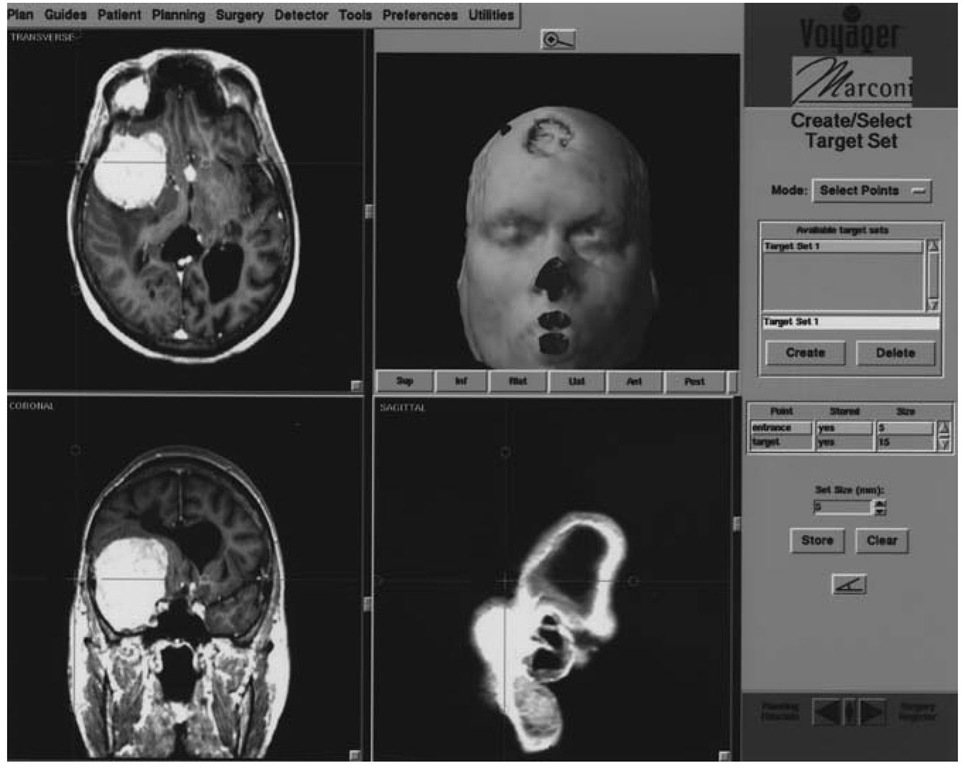
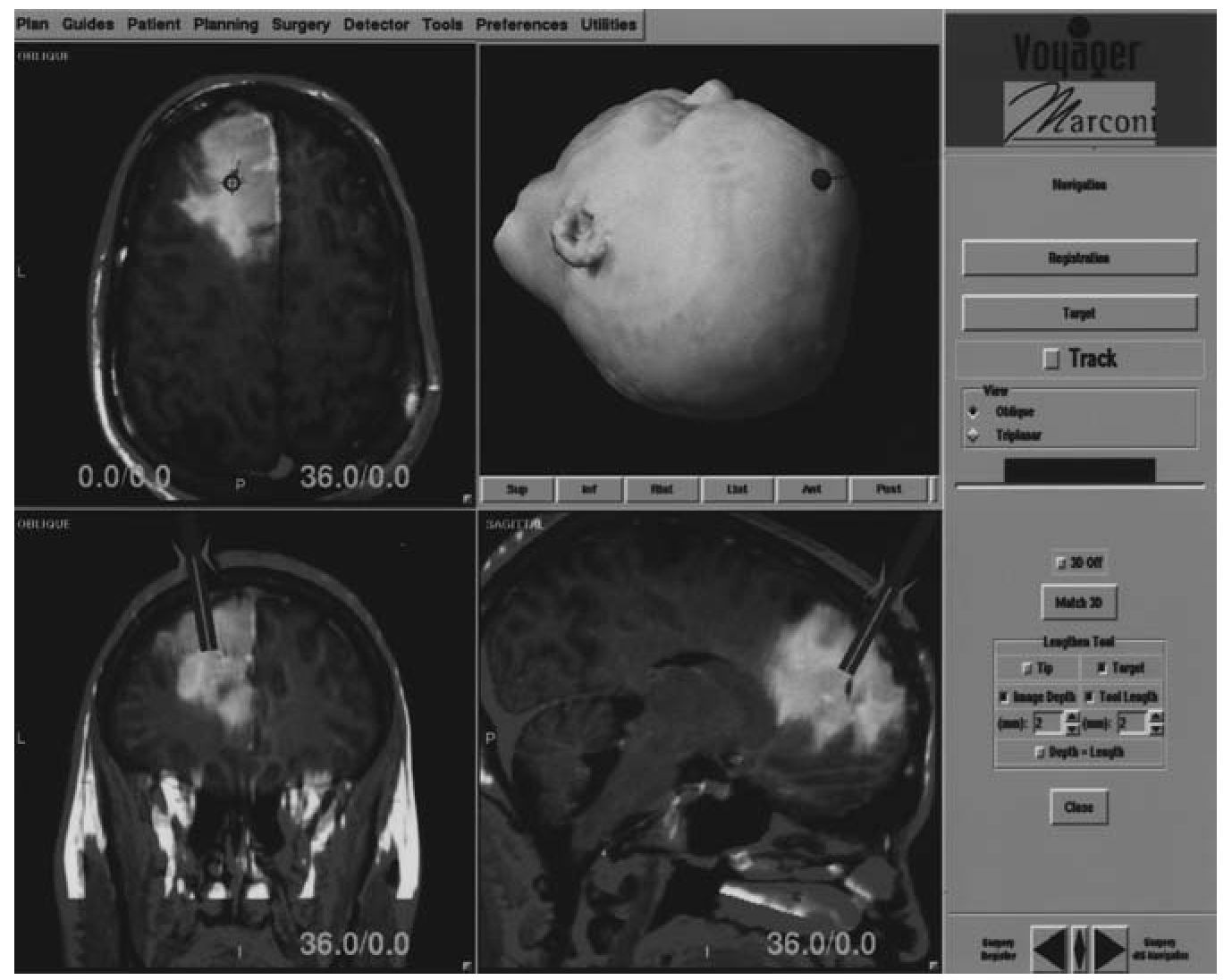
Two general displays are used, irrespective of whether the case is cranial or spinal. The first is a presentation of axial, coronal, sagittal and three-dimensional surface images (Fig. 7). The cross-hairs show the position of the tip with respect to the anatomy. The system may be set to run continuously, or intermittently (such as when stepping on the foot pedal). The oblique display (Fig. 8) presents images that are steered by the pointing device—two contain the axis of the pointer, the other is the plane perpendicular to the tip of the wand. This depth may be adjusted up or down by the foot pedal or be fixed at the depth of the target (if saved). The true and virtual positions of the tip are represented on the views that contain the wands. Navigation is then a straightforward process. Warnings are given if the wand, DRF, or both are out of view of the camera.
Figure 7 Typical triplanar display showing axial, coronal, and sagittal planes. This display provides localization function.
User Interface
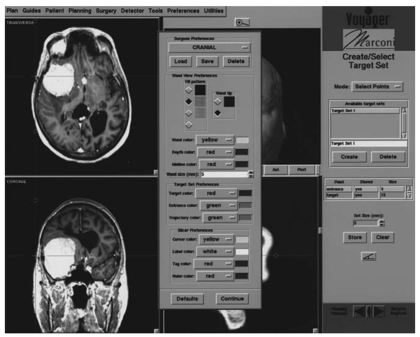
The user interface may be customized so as to suit the different needs of multiple surgeons. The colors, dimensions, and transparency of various items may be individually selected and saved. For instance, a surgeon performing predominantly spine surgery using CT may elect to use red for the wand (i.e., virtual screw) for best visualization, whereas an intracranial surgeon using MRI may prefer yellow to represent the wand.
Each panel has independent adjustments for the display attributes of the various image datasets in use, or they may be applied to all displayed planes. The attributes are ”remembered” when switching between different functions of the system.
Figure 8 Typical oblique display where wand or pointing device "steers" the display. Bottom row shows two (orthogonal) planes including axis of wand. Top left shows a plane perpendicular to axis of pointer. Top right shows three-dimensional representation of head with projection of wand out of surface.
Each dataset may be individually windowed, leveled, and colorized within a panel (Fig. 9). The zoom function for that panel applies to all image sets displayed in that panel. Unlike some systems in which use of fused datasets may only be manipulated or used during planning, Voyager allows the relative contribution of the image data sets to be adjusted for better anatomical, physiological, or metabolic visualization during navigation.
SUMMARY
The Voyager navigation system is the product of evolutionary development that provides simple, yet flexible and powerful navigation in the head and spine. The system and its creators have contributed several firsts to the field of surgical navigation and will continue to do so.
Figure 9 Many screen parameters may be adjusted for individual windows or the entire workspace. Colors and transparency of overlays may be stored as user preferences.


