Introduction
Modern stereotaxis implies that application of all space-defining devices to reach the selected target. The Zamorano-Dujovny (Z-D) stereotactic head frame (F. L. Fischer, Freiburg, Germany) was developed for several reasons: to provide a stable referencing system for several types of imaging studies, such as conventional X-rays, computed tomography (CT), magnetic resonance imaging (MRI), or digital subtraction angiography (DSA); freedom of choice for the surgeon on a patient’s intraoperative position; fully sterile draping; and an unobstructed approach for using conventional neurosurgical and microsurgical intraoperative techniques [1,2].
Open stereotaxis provides a wide variety of applications with varying degrees of sophistication, ranging from a simple localization tool up to a highly complex system for surgical automation and robotic applications. Since its inception, continuous improvements and accessories have become necessary to accommodate evolving technology in the field of image-guided stereotaxis.
The Zamorando-Dujovny Stereotactic System
The Z-D stereotactic system consists of an arc-centered frame, a carbon fiber base ring, and a localizer arc, also called an aiming bow. The system also accommodates multiple accessories and instruments, as well as optional software (Figs. 1 and 2).
Base Ring
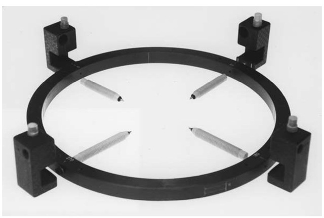
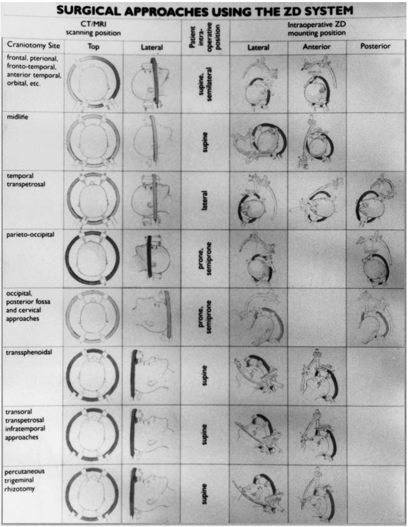
The base ring acts as a reference system and intraoperative head holder. The base ring can be made of aluminum, which is CT and X-ray compatible, carbon fiber, which is compatible with all imaging modalities (CT, X-ray, MRI, positron emission tomography (PET), or titanium, which is CT, X-ray, MRI, and convergent beam irradiation (CBI) compatible. The Z-D unit includes an open base ring, three or four pin holders that can be positioned at any desired location, and a set of 18 pins in five different lengths. The ring opening and different pin lengths make it possible to place the ring in any chosen position (Fig 3). When the unit is in place on the patient’s head the surgeon is provided with an unobstructed area within which to perform the craniotomy.
Figure 1 The carbon fiber ring, along with the posts and pins in pre-mounting position.
Figure 2 Phantom showing the superimposition of the retractors and the localizing unit for targeting.
The Localizer Arc
This unit consists of an arc quadrant that can be mounted in any of four positions on the base ring: at 0°, 90°, 180°, or 270°. The arc settings include three linear scales (a, b, c) and two angular scales (d, e). The first three correspond to the traditional x, y, and z spatial orientations. The last two are for modifying the entry point of the surgical trajectory according to the location of the lesion, vascular structures, and skull bone. The arc has two types of instruments holders, one for instruments 2 mm to 4 mm in diameter, and one for instruments 4 mm to 7 mm in diameter. The holders have a scale for depth adjustment. Several instruments can be adapted to the arc, including biopsy instruments (side-cutting and cup forceps), cannulae, he-matoma evacuators, electrodes, endoscopes, brachytherapy plates, and especially important for open stereotaxis, stereotactic brain retractors (cylinder and speculum types). The biopsy instruments include forceps 1.4 mm in diameter, a probe with a lateral cutting edge, a Backlund spiral probe, and a biopsy and seed applicator set.
Figure 3 Surgical approaches with the Zamorano-Dujovny (Z-D) system. Notice the versatility of the system for standard neurosurgical approaches.
The stereotactic brain retractors consist of 2-cm and 3-cm diameter cylinders and 3-cm and 6-cm length specula that open from 0 to 5 cm in diameter; a reading displays the actual opening diameter. Both bivalve and quadravalve specula are available, as well as a bayonet-type design that allows free access to the surgical corridor (Fig. 2).
Attachments
The concept of the stereotactic head frame as a localization device has evolved into the head frame as a sophisticated carrier-equipment unit. The ease with which the frame, along with the arc quadrant, can be manipulated allows the integration of different devices according to surgical necessity. The most basic attachment, the biopsy needle, can share an instrument holder with biopsy forceps. The inner guide of the needle biopsy can be applied as a stylet through which to position ventricular catheters for hydrocephalus and, at same time, for brachytherapy. The rigid endoscope (Chavantes-Zamorano Neuroendoscope, Karl Storz, Tuttlingen, Germany) can be adapted to the stereotactic arc, along with rigid and flexible endoscopic instrumentation. Laser fibers can access the surgical corridor from the arc and be advanced to reach targets for specific applications.
Imaging
During image acquisition, the base ring provides the attachment for the image localizers. Intraoperatively, the base ring acts as a head holder when used in conjunction with the Mayfield head holder and/or the Sugita adapter. For CT and MR imaging, adapters provide an isocentric relationship with the CT gantry and the MR imaging head coiler. Independent of the type of interfacing method selected between the imaging studies and the base ring (isocentric or localizing), the reference for target localization will be the center of the ring, which defines the point origin of the stereotactic space.
X-ray Localization
X-ray localization is performed using orthogonal X-ray tubes, which are securely mounted in a lateral and anteroposterior (AP) position and are aligned with the head ring of the stereotactic system. When the system is installed, the lateral AP tubes are positioned so that their central beam passes through the holes of the head ring at 0° and 180° (AP) and at 90° and 270° (lateral). In order to limit magnification, the X-ray tubes should be mounted at a relatively large distance from the head ring. After the X-rays have been taken and developed, the coordinates for the x and z axes are obtained from the AP X-ray and the coordinates for the y and z axes for the target and trephination points are taken from lateral X-ray.
Angiographic Localization
Four quadrangular localizer plates are positioned and screwed to the head ring to allow X-ray views for localizing vascular structures. A fifth plate is used intraoperatively; when the Z-D localizer arc is mounted on the head ring, it takes the position where a localizing plate could be fastened. The Z-D setting module has two additional holes in which to insert localizer plate #5. After the X-ray films are taken, they are placed on a digitizing tablet; the desired target and trephination points are digitally determined and transferred automatically to a personal computer (PC) using the Angioloc 650 056 computer program. The program compensates for magnification error and determines the angle of incidence obtained from visible points on X-ray or angiographic films.
The Angioloc program includes an Angiorev program that accepts ste-reotactic coordinates already determined from CT or MRI scans and adds them to the X-ray/angiographic image. This proves important for stereotactic biopsy in a highly vascular area. The Angiorev program allows the surgeon to determine if the biopsy needle is likely to pierce a vessel on its way from the entry point to the target point.
CT, MRI, and PET Localization
For CT and PET localization, the head ring is attached to the CT adapter. Four specially designed plates are mounted and screwed to the ring (Fig. 1). The CT scan usually includes the alignment of the cursor of the gantry to the top of the arc in axial direction generating image acquisition in positive or negative direction according to the specific circumstances. Our setup parameters are to position the table at 175 mm, zeroing the gantry, and proceeding 200 mm forward.
For MRI localization, localizing plates are attached to the four quadrants that define the anatomical space, yielding a set of coordinates. Sequences and protocols can be flexible, according to the specific circumstances, but in general the authors use T1-, T2-, proton densities, and 2-mm slice thickness for tumor surgery with extra three-dimensional flash in functional cases.
Software: The Preoperative Planning Process
The original concept of applying the frame to approach tumor resection has shifted to a more broad-based application in neurosurgery. Nevertheless, the majority of neurosurgical procedures begin with the preoperative planning process. We’ve developed PC-compatible software, the Neurosurgical Planning System (NSPS), that provides settings for mounting the Z-D localizer arc in any position. The extensive capabilities of the software allow the surgeon, during the preoperative planning process, to select imaging modalities interactively, define tumor volumes of interest, select entry and target points, and calculate the stereotactic coordinates that translate into a physical target.
The first set of coordinates are determined by the surgical approach, surface vessel pattern, and cortical brain anatomy. The second set of coordinates are chosen according to tumor pathology, biopsy specimen, and tissue sampling that includes pathological tissue and its interface with normal brain tissue.
Assembling The Z-D Frame-Based System For Surgery
Mounting the Z-D Localizing Unit
The patient is prepared for mounting the Z-D unit: vital signs are monitored, an intravenous (IV) line is placed for sedation with Versed® 2 mg and Fen-tanyl® 100 mcg, and supplemental oxygen is provided. The ring is placed in the clamps of the head holder. The patient is put on the stretcher and carefully moved into the ring. The patient’s head is positioned such that the ring is parallel to the obtitomeatal line.
The sites of pin placement are marked, and efforts are made to accommodate the frame at the same level. With the head frame in place, imaging studies are taken with the patient maximally positioned with regard to the lesion. The arc quadrant is mounted by fastening the basic carrier to the head ring. Then the ring slides into the axle mounting cross so the 1.1 numbers are exactly opposite. The right-angled drum axle is also inserted to the axle mounting cross. The aiming bow is positioned over the drum of the axle mounting cross. The aiming bow is turned by slightly pushing it until the guide pin locks in the guide groove. The instrument holder is positioned onto scale "E" on the arc of the aiming bow. The instrument carrier in inserted into the dovetail guide on the instrument holder and fastened to "0” on the depth control. An additional carrier is attached to the smaller dovetail guide and screwed down until it juts out at a 90° angle. A target point with a positive z coordinate (above the ring) is reached when the F. L. Fischer label on the fixation rail points in this direction.
By loosening one screw (D) on the stereotactic ring, the neurosurgeon can bring the localizer arc in and out of the surgical field to check the localization and the depth of the resection ("nonfixed" open stereotaxis). This feature is especially useful for craniotomies to treat superficial lesions located in eloquent areas of the brain. The nonfixed approach is also helpful for craniotomies of deep lesions using a microsurgical approach, allowing the neurosurgeon to operate using standard neurosurgical techniques while evaluating the intraoperative target localization. In addition, when a nonlinear pathway to a lesion is preferred, such as in transcallosal, lobe retraction, transoral, and skull base surgery, the surgeon performs the approach using microsurgical techniques and, when close to the target area, uses the d and e screw to guide the probe further along the defined surgical pathway.
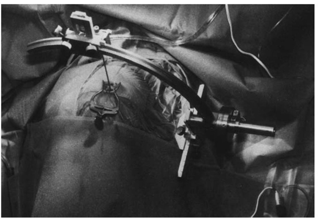
For ”fixed” open stereotaxis, useful for removing deep-seated lesions when a lineal transcortical or transcerebellar corridor is desired, the arc settings on the Z-D localizer unit (a,b,c,d,e) are kept fixed during the intracra-nial surgical procedure, and specially designed stereotactic brain retractors are mounted in the instrument holders. These consist of 2- and 3-cm diameter cylinders and a 6-cm long speculum; the last one opens from 0 to 5 cm in diameter. Both types of brain retractors are designed with a bayonet-type holder that allows an unobstructed surgeon’s eye or microscope view line, as well as ample room for conventional surgical instruments like mi-croinstruments, a laser, an ultrasonic aspirator, and others. The instrument holder scale allows continuous depth adjustment of surgical instruments (Fig. 4).
The Multiple Applications of The Z-D Frame
Z-D Frame in the Resection of Gliomas
Needle biopsy using the Z-D unit significantly enhances the information gathered by imaging studies regarding tumor dimensions, location, and depth. During biopsy, the forceps are inserted through a guide cannula, and the combined instrument is placed in the instrument carrier on the Z-D localizing arc.
We use the Z-D system with a real-time intraoperative digitization system to operate on gliomas [3]. Intraoperative digitizers are instruments through which a physical correlation between the image modality data (CT and MRI) and the patient’s neuroanatomy is made so that intraoperatively, instruments can be tracked using an optoelectronic camera system. In the operating room, interactive image-guided surgery begins with instrument calibration using infrared cameras and a digitizing probe. When using the stereotactic frame as a reference point, the probe touches predefined points in circumferential fashion on the Z-D ring, establishing coordinates that match those derived from imaging studies and plotted using the NSPS software program during the preplanning process. Multiple trajectories can be chosen to approach the tumor sequentially in the resection, to aspirate cystic portions, for ventricular tapping, or to place a ventricular drain.
Figure 4 Intraoperatively, mounting the localizing unit and positioning the biopsy needle.
Brachytherapy
The planning process combines volume rendering and isodose planning to calculate number of catheters and seeds loading. Radioactive seeds can be placed subsequent to stereotactic biopsy. Inner coaxial catheters are preloaded with the seeds. The introduction of an external ventricular guide is accomplished following the guidelines. Subsequently, the catheter is glued to the bone continuing with the inner coaxial placement. Hemoclips are applied to secure it. Quality assessment protocols allows strict evaluation of postoperative placement [4].
The Z-D System in the Resection of Vascular Lesions
From all the group of arteriovenous malformations, cavernous angiomas are characterized by their clinical behavior, pseudocapsule formation, and from an origin intermingled at any level of the white matter where accurate localization is cumbersome. The biopsy needle can be advanced to locate the upper margin, depending on the size of the lesion, to continue with micro-surgical dissection to resect in toto. Multiple lesions can be resected without increased morbidity and especially for seizure control [5].
Z-D Stereotactic Frame in Ventricular Approaches
This category of approaches deserves special mention, given the frequent distortion once the ventricle has been entered. The optimal approach is to select the target for sampling, ventricular catheter placement, or to bring the endoscope to the microsurgical field. We pay attention to the position of the patient, neutral in coronal approaches and completely lateral in temporal horn or occipital approaches. In the posterior fossa we use the prone position specifically for midline approaches. Again it is very important not to open the ventricle until we have available all equipment for the procedure. The stylet is used to guide the catheters marking 19 cm from the tip to the upper margin. We call attention to the fact that target zero is not in the tip of the needle but in the center of the slit aperture [6].
The Z-D Stereotactic Frame in Trigeminal Rhizotomy
Trigeminal neuralgia is another important application when targeting is essential, especially in transfacial pretrigeminal cistern approaches. Computed tomographic scan is the preferred imaging modality. The entry point can be selected in the 1 foramen to direct the needle. Electrodes can be inserted to confirm the position of the needle before lesioning with the radiofrequency generator (Neuro50, F. L. Fischer, Freiburg, Germany).


