Introduction
Various skeletal parts provide valuable data on individual human characterization of unknown remains, particularly the skull. In criminal cases, the identification of skeletal remains is frequently carried out by skull-photo superimposition because a facial photograph can be easily obtained from the victim’s family. The skull-photo superimposition technique is considered to be reconstruction, in that it attempts to supply a facial photograph for a discovered unknown skull. In order to identify someone through the superimposition technique, the examiner must investigate the outline and positional relationships of the skull to face parts, based on anatomical data after the skull to comparison photograph orientation is achieved.
From the forensic standpoint, the most instructive example of the application of this technique is provided by the two skulls from the Ruxton murder case of 1935 in England. In this case, there were two female skulls, listed as skull no. 1 and skull no. 2. It was assumed that one was that of Mrs Ruxton and the other belonged to the housemaid Mary Rogerson. Comparisons using a superimposition technique in Mrs Ruxton’s case demonstrated that skull no. 1 could not possibly be the skull of Mrs Ruxton, and that skull no. 2 might be the skull of Mrs Ruxton. In Miss Rogerson’s case, the comparisons demonstrated that skull no. 2 could not possibly be the skull of Miss Rogerson, but that skull no. 1 might be the skull of Miss Rogerson. As a general rule, it can be stated that superimposition is of greater value in ruling out a match between the skull and facial photograph; however, researchers are led to believe that skull-photo superimposition is an efficient method for identifying the unknown skull because facial photographs are routinely used as a reference object of the victim. Of course, in some cases a facial photograph of another person may well be consistent with the skull in question in the outline and anatomical relationships between the skull and face. Therefore, forensic examiners must be well versed in the anatomy of the skull and face for effective utilization of the superimposi-tion technique.
Anatomical Relationships between Skull and Face
When evaluating anatomical consistency between these parts, special attention should be paid to their outline, the facial tissue thickness at various anthro-pometric points, and the positional relationships between skull and face.
Thickness of facial soft tissue
The thickness of facial soft tissue is one of the important factors in reconstructing the face of an unknown skull. Several methods, such as puncturing, radiography, ultrasonic probing and computed tomography, are used for measuring soft-tissue thickness on the various anthropometric points of the head. Data on the thickness of facial soft tissue have been accumulated for each race: Caucasoid, Negroid and Mongoloid. Tables 1 and 2 on pages 784 and 785 summarize this data. In the application of superimposition, examiners should first investigate the contours of both skull and face, and then must take into account soft-tissue thickness on various points and evaluate its individual variation (Fig. 1).
Positional relationships between skull and face
Relation of eyebrow to supraorbital margin The lower border of the eyebrow is generally located on the supraorbital margin. According to some researchers, the placement of the eyebrow is approximately 35 mm above the supraorbital margin.
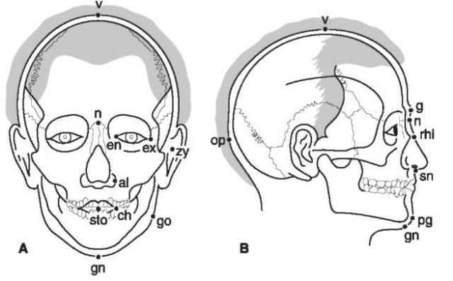
Figure 1 (A) Frontal and (B) lateral views of the head showing landmarks for the examination of consistency between a skull and a facial photograph by the superimposition method, al, Ala; ch, cheilion; en, entocanthion; ex, ectocanthion; g, glabella; gn, gnathion; go, gonion; n, nasion; op, opisthocranion; pg, pogo-nion; rhi, rhinion; sn, subnasale; sto, stomion; v, vertex; zy, zygion,
Relation of eye to orbit In vertical placement, the eye slit (palpebral fissure), which is the line connecting the inner canthus (entocanthion) and the outer can-thus (ectocanthion), falls approximately on the lower third of the orbital height (Fig. 2). The vertical level of the inner canthus corresponds approximately to the point of attachment of the medial palpebral ligament; this point is located about 10 mm below the dacryon, the junction of the lacrimomaxillary, frontomaxillary and frontolacrimal sutures. The position of the outer canthus corresponds to the point of attachment of the lateral palpebral ligament; this point is called the ‘malar tubercle’ and is located about 11mm below the point at which the zygomaticofrontal suture crosses the orbital margin. The position of the outer canthus is slightly higher than that of the inner can-thus (Fig. 2). In horizontal placement, the inner can-thus is positioned more than 3 mm lateral to the medial orbital margin (approximately 5 mm), and the outer canthus lies on or slightly within the lateral orbital margin (Fig. 2).
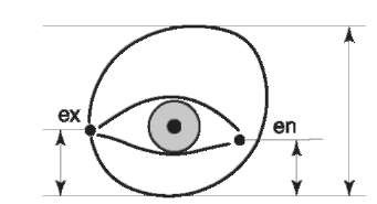
Figure 2 Relation of the eye to the orbit, The eye slit lies on the lower third of the orbital height. The entocanthion (en) lies more than 3 mm lateral to the medial orbital margin. The ecto-canthion (ex) lies on the lateral orbital margin or inside it,
Relation of external nose to nasal aperture The height of the nasion-subnasale (external nose) corresponds to that of the nasion-subspinale on the skull, although the subspinale and subnasale do not lie at the same level. There is a difference in the two measurements favoring the external nose, which averages 1.4 mm in the adult Caucasoid and 1.6 mm in the adult Negroid. In the Mongoloid, the position of the rhinion corresponds to the upper third and the position of the nasospinale corresponds to the lower seventh of the nasion-subnasale height (Fig. 3). The measurement of the width of the external nose (ala to ala) always exceeds that of the nasal aperture. In general, alae lie 5 mm lateral to the lateral margin of the nasal aperture in the Caucasoid, 8 mm in the Negroid, and 6.5 mm in the Mongoloid (Fig. 3).
Relation of lips to teeth At rest, the oral slit appears to coincide with the line formed by the bite. The central point of the oral slit (stomion) falls 1-2 mm higher than the cutting margin of the upper central incisor. The oral angle (cheilion) generally lies on the junction of the canine and the first premolar. The average distance between the upper and lower teeth in repose is about 3 mm at both the first premolar and the first molar.
Relation of ear to porus acusticus externus The porus acusticus externus is generally located just behind the tragus. According to some researchers, the relation of the most lateral part of the cartilaginous portion to the bony portion of the ear tube is 5 mm above, 2.6 mm behind and 9.6 mm laterally.
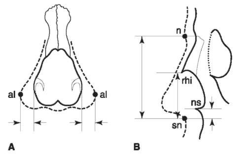
Figure 3 Relation of the external nose to the nasal aperture. (A) The average distance from the lateral margin of the nasal aperture to the ala (al) is 5 mm in the Caucasoid, 8 mm in the Negroid and 6.5 mm in the Japanese. (B) The position of the nasospinale (ns) corresponds to the lower seventh of the height of the external nose (n-sn).
Technical Development
From the aspect of technical development, skull-photo superimposition can be seen to have passed through three phases: the photographic, video and computer-assisted superimposition techniques. The photographic superimposition technique was developed in the mid-1930s. Since the latter half of the 1970s, the video superimposition technique has been widely used in the field of forensic anthropology and odontology. Computer-assisted superimposition was introduced in the latter half of the 1980s. In all techniques, the two most important factors are the enlargement of the facial photograph and the alignment of the skull to the photograph.
Photographic superimposition
When performing photographic superimposition, the examiner must always enlarge the comparison photographs to the size of the unknown skull and then position the skull in the same orientation as the facial photographs.
Enlargement of facial photograph Enlargement of facial photographs has been accomplished by employing measurable objects for the enlargement scale, facial proportion and distances, and anatomical landmarks on the skull and face. For instance, a magnification factor may be calculated from various measurements of the chair and the width of the collar in a photograph, and a life-sized facial photograph of the individual is reproduced. When the anterior teeth are seen in a facial photograph, the known sizes of anterior teeth in an unknown skull are used to decide the magnification factor for the facial photograph. In the use of anatomical landmarks, the frontal view facial photograph is enlarged from the original photograph based on bizygomatic skull width and soft-tissue thickness of the zygion. In the oblique or lateral view, the facial photograph enlargement is based on glabellagnathion distance and the soft-tissue thickness of the gnathion.
Orientation of skull to facial photographs A cranio-phore used for anthropometry and a pivoting head tripod are most commonly used for positioning the skull. To date, a number of devices have been designed to position the skull so that it will adjust to the orientation of the facial photograph. The pulse motor-driven skull rest has been developed to solve the orientation problem. The skull rest can be moved by remote control levers in six directions: upwards and downwards, left and right, forwards and backwards, rotation around the axis, extension and flexion, and tilt to the left and right. The combination of these movements adequately establishes the orientation of the skull to multipositional facial photographs. The skull rest is also used for both video and computer-assisted superimposition techniques.
Procedure for photographic superimposition ‘Seeing through’ techniques, in which orientation of skull to facial photograph is achieved by looking through a transparent face film, are optimal for photographic superimposition. The simplest method is to use the ground glass of the camera as a transparent plate. An original available photograph is taken and reproduced on quarter-size cut film. The negative thus obtained is placed under the ground glass of the camera, and the outline of the face is drawn using very fine pen and Indian ink. A 1 inch scale is placed on the forehead of the skull on a suitable skull rest, so that the skull may be arranged in the same perspective as the portrait. The skull is then photographed on quarter-size cut film. The negative is enlarged to natural size, so that the image of the 1 inch scale is exactly 1 inch, and then printed on bromide paper. A positive transparency is then taken on 24 x 30 cm X-ray film. Finally, the natural-size transparency of the skull and the life-size transparency of the portrait are superimposed and photographed on quarter-size cut film using transmitted light. An optical bench has been manufactured for the ‘seeing through’ method, consisting of a skull rest, a frame with criteria lines (rubber bands), a thin plastic plate and a camera. The skull is fixed at one side of the optical bench, and the camera at the other. The appropriate anthropometric points (e.g. nasion, gnathion, gonion, zygion, etc.) are marked on an enlarged facial photograph and then three guidelines are drawn, based on these points with India ink. Three criteria lines within the frame are adjusted to the guidelines on the facial photograph. The outline of the head and the guidelines are drawn on the thin plastic plate. When the criteria lines of the frame coincide with the guidelines on the thin plastic plate, the skull position is set, taking soft-tissue thickness into account. The enlarged facial photograph without the marker points and the guidelines is set on to the thin plastic plate, and then photographed. Finally, removing the frame and thin plastic plate, a double exposure of the positioned skull is taken.
In the 1980s, special apparatus for superimposition were devised. An example of such an apparatus reproduces the skull on the ground glass in half the original skull size via four plates of reflective mirror and a projection lens (Fig. 4). The comparison facial photograph is also reproduced at half the original face size according to anatomical landmarks. The image of the skull on the ground glass is then photo-graphed using a cabinet-size film. The skull and face films are finally superimposed on the light box (Fig. 5).
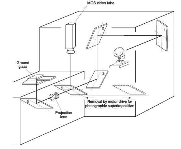
Figure 4 Illustration of the optical pathway. The optical pathway is produced by the combination of four reflection mirrors. For photographic superimposition, the fourth mirror is designed to slide out of the optical pathway in order to focus the skull image on the ground glass via a projection lens and mirror (5); for video superimposition mirrors 1-4 are used and the skull image is taken with a video camera.
Video superimposition
It has been suggested that video superimposition provides an enormous advantage over the usual photographic superimposition, in that comparisons can be made rapidly and in greater detail than is possible with static photographs. In general, the video superimposition system consists of a skull-positioning rest, two video cameras (1 and 2), a video image mixing device, a TV monitor and a videotape recorder (Fig. 6). The skull is first filmed with video camera 1 and reproduced on the TV monitor through the video image mixing device. The facial photograph is then reproduced on the TV monitor using video camera 2. Some laboratories use two video cameras, electronic and mixer units and three monitors. The skull is taken with camera 1 and the image is reproduced on monitor 1. The facial photograph is then reproduced with camera 2 on monitor 2. The mixed picture and horizontal and vertical sections are punched up on monitor 3 by means of the electronic and mixer units. To make the comparison, the skull image is superimposed on the facial image, and then adjusted to match the orientation of the face by the motor-driven mechanism described above. The size of the skull image is easily adjusted to that of the facial image using the zoom mechanism of camera 1, taking soft-tissue thickness into account. This technique permits fade-out and fade-in of the image of either the skull or face on the monitor for overall assessment of how well the two images match (Fig. 7). It also allows sectioning of the various images of the skull and facial images on the monitor (Fig. 7). The fade-out and wipe images, especially the latter, facilitate the comparison of positional relationships between the skull and face. However, in the video superimposition, the thickness of soft tissue at the anthropometric points and the distance between the anatomical landmarks cannot be directly evaluated on the monitor. The superimposed image on the monitor can be photographed directly with the camera or permanently preserved on videotape.
Computer-assisted superimposition
As computer technology advances, computer-assisted superimposition has become a popular method of identifying the unknown skull. Computer-assisted superimposition is divided roughly into two categories from the point of view of identification strategy. The first method is to digitize the skull and facial photograph using a video computer with appropriate software and then to compare the two images morphologically by image processing. Establishing a scale for the digitized skull image is performed by converting the actual measurement between the land- marks (e.g. zygion-zygion, nasion-gnathion, etc.) into the number of pixels on the monitor. For the assessment of anatomical consistency between the digitized skull and face, the distance between the anatomical landmarks and the thickness of soft tissue at the anthropometric points are measured semiauto-matically (Fig. 8). The software allows for fade-out and fade-in of the image of either skull or face, or wiping either the skull or face in the vertical or horizontal plane for evaluating anatomical relationships between them (Fig. 8). Some researchers have developed a methodology for comparing the skull and facial image using the near optimal fit between the three-dimensional skull surface mesh and the two-dimensional digitized facial photograph.
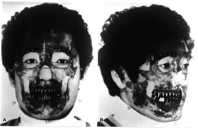
Figure 5 (A) Frontal and (B) oblique photographic superimposition images, showing a good match between skull and facial photographs.
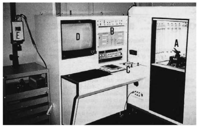
Figure 6 Video superimposition system. A, Skull-positioning box; B, electronic and mixing devices; C, control panel with joystick levers and momentary paddle switch; D, TV monitor; E, photo-stand for taking the facial photograph.
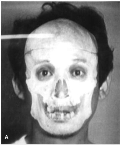
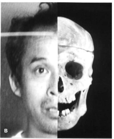
Figure 7 Video superimposition showing (A) total mixing and (B) vertical wipe images of the skull and facial photograph.
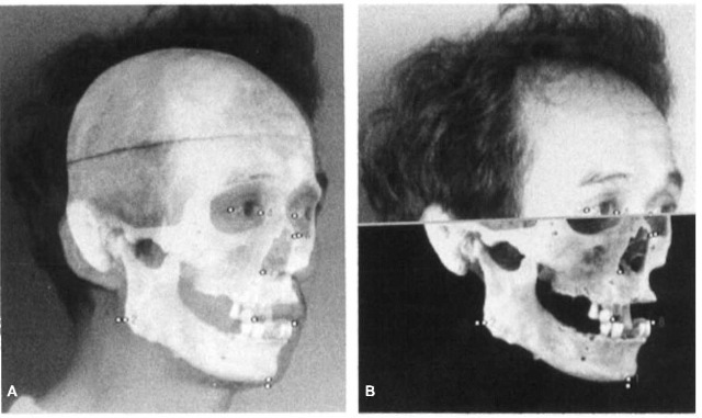
Figure 8 (A) Total mixing and (B) horizontal wipe images showing comparison between the digitized skull and face. The thickness of soft tissue of the anthropometric points and the distance between the anatomical landmarks are measured by means of pair-dots using the mouse.
The second method is to evaluate the fit between the skull and facial image by morphometric examination. For instance, polynomial functions and Fourier harmonic analysis are applied to assess the fit between the outline of the skull and the face (Figs 9 and 10). If quantitative data based on morphometric analyses are obtained in addition to the anatomical and anthropo-metric evaluation, the judgment of skull identification will be more objective and reliable.
A new approach for judging the match between the skull and a facial photograph examines mathematically the coordinate values of the paired anatomical landmarks of the skull and face.
Evaluation of Consistency between Skull and Face
It is generally accepted that the unknown skull without the mandible cannot positively be identified as the presumed person, even if a good match is seen in the skull-photo superimposition image. The complete skull is required to obtain any degree of certainty.
The skull-photo superimposition should be able to prove whether or not the skull and facial photograph belong to the same person. In general, it is considered that the skull-photo superimposition is more valuable for exclusion purposes, because it may be definitely stated that the skull and facial photograph are not those of the same person. However, if they are well matched with each other, it can only be stated that the skull could be that of the photographed person. This is because of the possibility that this skull may be consistent with the facial photograph of another person, or another skull of the same size and contour may be consistent with the face of the photographed person. Experimental studies on the reliability of skull-photo superimposition suggest that a false match is almost always excluded when both frontal and lateral view photographs are compared with the skull. Unfortunately, it is often difficult to obtain a lateral view photograph in actual cases, and oblique view photographs are used to enhance the degree of consistency between the skull and face. Skull-photo superimposition must be considered highly corroborative, almost conclusive for personal identification when two or more photographs, clearly depicting the facial features from different angles, are used in the comparison. The outline from the forehead (trichion) to the gnathion in the lateral or oblique view is the preferred portion for identification.
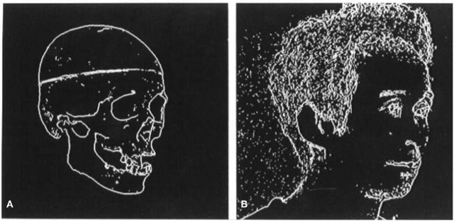
Figure 9 Thinning images extracted from (A) the digitized skull and (B) facial images. The forehead region of the thin line is selected for evaluating the fit between the contour of the skull and face.
When the incisors and canines can be seen in the facial photograph, they can be used as reliable data. The coincidence of dentition between the skull and facial photograph could lead to positive identification. Pathological findings or congenital abnormalities in the skull and facial photograph, in addition to points of consistency between the skull and photograph, certify that they belong to the same person.
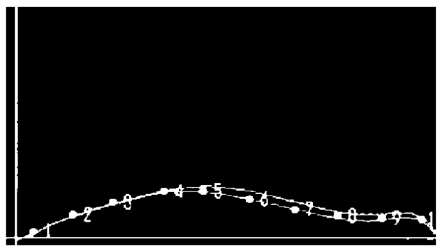
Figure 10 Polynomial function curves obtained from the forehead line in Fig. 9 showing a good match and 10 measurement points for calculating the distance between both curves.
