24.9.
Centrifugal Clutch
24.9.1.
Semi-centrifugal Clutch
This type of clutch uses lighter pressure plate springs for a given torque carrying capacity, so that the engagement of the clutch in the lower speed range becomes possible. The centrifugal force supplements the necessary extra clamping thrust at higher speeds.
Offset bob weights are attached to the release levers at their outer ends, allowing levers to be centrifugally out of balance (Fig. 24.19). The centrifugal force causes the pressure plate to force against the driven plate, adding extra clamping load. Although the thrust due to the clamping springs is constant, the movement due to the centrifugal force varies as the square of
the speed (Fig. 24.20). Therefore, the reserve factor for the thrust spring can be reduced to 1.1 compared to 1.4-1.5 for a conventional helical coil spring clutch unit. Consequently, centrifugal clutch can be used for heavy duty applications requiring transmission of greater torque loads.

Fig. 24.19. Semi-centrifugal clutch.

Fig. 24.20. Semi-centrifugal clutch characteristics.
24.9.2.
Fully Automatic Centrifugal Clutch
Fully automatic centrifugal clutches smoothly take up the drive from engine idling with a progressive reduction in slip within a narrow rising speed range until sufficient engine power is developed to propel the vehicle directly. Above this speed full engagement of clutch takes place.
For carrying out gear changes during vehicle movement, a conventional clutch release lever arrangement is additionally incorporated, which enables the driver to disengage and engage the clutch independently of the flyweight action.
A reaction plate is installed in between the pressure plate the cover pressing in the automatic centrifugal mechanism. Four equally spaced bob-weights (Fig. 24.21) are attached to this reaction plate through pivot pins, about which they rotate as centre of gravity is on one side of the pins. When the engine speed increases, the bob weight tends to fly outward. The rotational movement of the bob weight is partially prevented by short struts offset to the pivot pins so that this movement and effort are relayed to the pressure plate. At the same time, the reaction plate compresses both the reaction and pressure springs due to the reaction to this axial clamping thrust causing it to move backwards towards the cover pressing. The greater the centrifugal force, more the springs are compressed and their reaction thrust becomes larger, which increases the pressure plate clamping load.
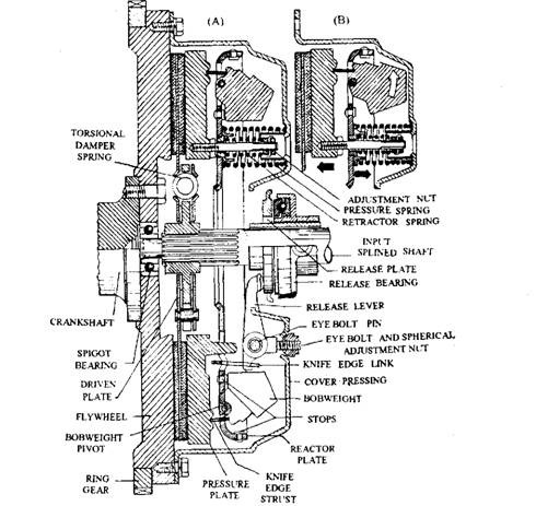
Fig. 24.21. Fully automatic centrifugal clutch.
For achieving the best pressure plate thrust suiting to engine speed characteristics (Fig. 24.22), adjustable reactor springs are installed, which counteract the main compression spring reaction. The initial compression length for loading of these springs is set up by the adjusting nut after assembly of the whole unit. The resultant thrust of both sets of springs control the actual take-up engine speed of the clutch.
Gear changes are made by moving the release bearing forwards during the disengaged position of the clutch. This causes the reactor plate to move rear wards by means of the knife-edge link and also withdraws the pressure plate through the reactor springs to release the pressure plate clamping load.
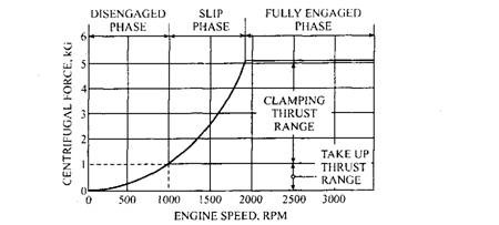
Fig. 24.22. Fully automatic centrifugal clutch characteristics.
24.9.3.
Torque Transmitted
A simplified centrifugal clutch is shown in Fig. 24.23A and enlarged view of section is shown in Fig. 24.23B. A cylindrical clutch casing contains four heavy blocks or shoes, which form the friction surfaces. The driving member consists of. a spider carrying the four shoes, which are kept away from contact with the clutch case by means of the flat springs. Engagement of the clutch takes place when the centrifugal force overcomes the resistance of the springs. The power is transmitted by friction between the surfaces of the shoes and the clutch case.
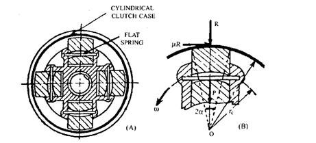
Fig. 24.23. Automatic centrifugal clutch (simplified).
The intensity of pressure between the contact surfaces is assumed to be uniform and also the angle subtended at the centre, O, by the arc of contact is assumed to be small. In fact the assumption of uniform intensity of pressure is not strictly correct. The tangential friction force causes the tilting of the radial guides. Thus the resultant radial pressure on each shoe shifts from the centre line of the shoe.
Let, p = the permissible intensity of normal pressure on the lining, Pa
2a = the angle subtended at the centre by the effective arc of contact, degrees
b = the width of the clutch plate surface, m
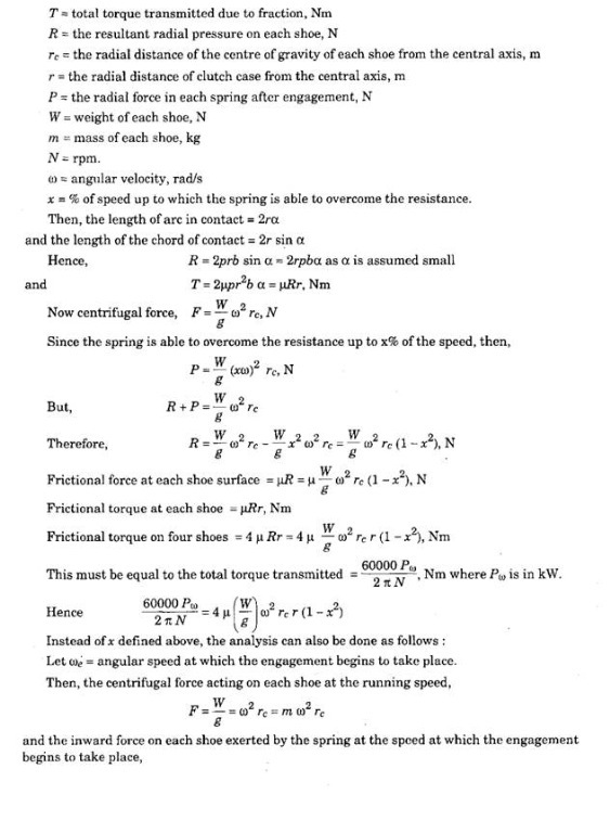
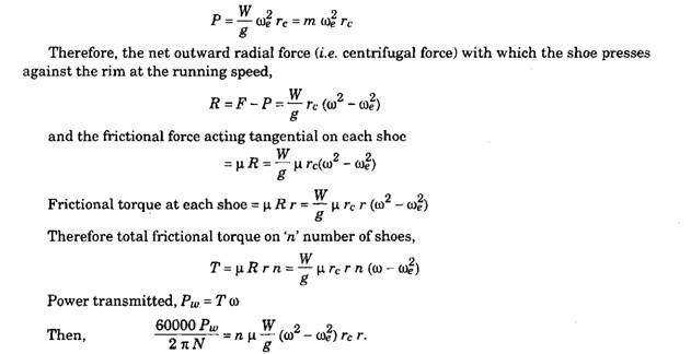
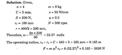
Normally radial clearance between the shoe and the rim being very small as compared to rc, it is neglected. If, however, the radial clearance is given, then the operating radius of the mass centre of the shoe from the axis of the clutch, r0 = rc + C, where C = radial clearance.
In order to ensure normal life, the intensity of pressure, p may be taken as 9.81 x 10⁴ N/m2.
Example 24.4. A centrifugal clutch has four shoes which slides radially in a spider keyed to the driving shaft and make contact with the internal cylindrical surface of a rim keyed to the driven shaft. When the clutch is at rest, each shoe is pulled against a stop by a spring so as to leave a radial clearance of 5 mm between the shoe and the rim. The pull exerted by the spring is then 500 N. The mass centre of the shoe is 160 mm from the axis of the clutch.
If the internal diameter of the rim is 400 mm, the mass of each shoe is 8 kg, the stiffness of each spring is 50 Nlmm and the coefficient of friction between the shoe and the rim is 0.3, find the power transmitted by the clutch at 500 rpm.
