24.10.
Fluid Couplings
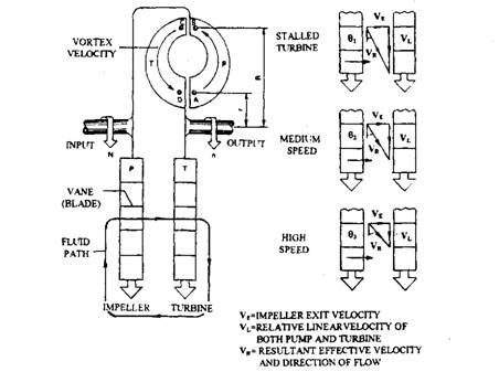
The hydrokinetic fluid coupling, also called as a fluid flywheel, uses two saucer-shaped discs, an input impeller (pump) and an output turbine (runner). Both impeller and turbine are cast with a number of flat radial vanes (blades) to direct the flow path of the fluid (Fig. 24.24). The hydrokinetic coupling works on the principle of relative slip between the input and output member cells facing to each other, and the continuous alignment and misalignment of the vortex flow path, created by pairs of adjacent cells, with different cells.

Fig. 24.24. Fluid coupling action.
If the impeller and turbine have equal numbers of cells, the relative cell alignment of all the cells occurs together so that a jerky transfer of torque from the input to the output drive occurs. With unequal numbers of cells in the two half members, the alignment of each pair of cells at any one instant is slightly different. This causes the impingement of fluid from one member to the other in various stages of circulation, so that the coupling torque transfer becomes progressive and relatively smooth.
The two half members are put together to obtain vortex flow of the fluid. In the earlier designs, normally a hollow core or guide ring (sometimes called as the torus) was inserted at the centre of rotation within both half-members to initiate early fluid circulation once the relative rotation of the members has been established. However, these couplings produced considerable drag torque during idling. Consequently only one core guide was used on the impeller member (Fig. 24.25) to reduce turbine drag at low speeds. In the latest design these cores are totally eliminated even to reduce fluid interference in the higher speed range. As a result the degree of slip for a given amount of transmitted torque (Fig. 24.29) is also reduced.

Fig. 24.25. Fluid coupling.
24.10.1.
Principle of Operation
During starting of the engine, the rotation of the impeller (pump) causes the working fluid trapped in its cells to rotate with it and due to centrifugal force, the fluid is pressurized and flows radially outwards. To understand the principle of the hydrokinetic coupling, circulation of a small fluid particle between one set of impeller and turbine vanes at various points A, B, C and D is considered as shown in Figs. 24.24 and 24.26.
When the engine is started and hence the impeller is rotated, a particle of fluid at point A experiences a centrifugal force due to its mass and radius of rotation r, so acquires some kinetic energy. This particle of fluid is forced to move outwards to point B at radius, R, so that it is subjected to relatively more centrifugal force thereby acquiring a greater amount of kinetic energy. At this outermost position, due to high kinetic energy, the particle is ejected from the mouth of the impeller cell, and is forced to enter one of the outer turbine cells at point C. During
this process the particle reacts with the turbine vanes and imparts some of its kinetic energy to the turbine wheel. Continuous fling of fluid particles across the junction between the impeller and turbine cells force the first fluid particle in the slower moving turbine member with reduced centrifugal force, to move inwards to point D. In the process of moving from R to r, the fluid particle imparts most of its kinetic energy to the turbine wheel, which ic subsequently converted into propelling effort and motion. The fluid under circulation contains two motions; firstly it is circulated by the impeller around its axis and secondly it circulates round the cells in a vortex motion.

Fig. 24.26. Principle of the fluid coupling.
This circulation of fluid continues till the centrifugal force possessed by the fluid in the faster moving impeller supersedes the counter centrifugal force acting on the fluid in the slower moving turbine member. The velocity of the fluid around the axis of rotation of the coupling increases as it flows radially outwards in the impeller cells. On the other hand the fluid velocity decreases when it flows inwards in the turbine cells and hence gives up its kinetic energy to the turbine. Therefore transference of energy from the input impeller to the output turbine takes place in the process, without any torque multiplication.
24.10.2.
The Velocity Diagrams
The resultant magnitude and direction of the fluid leaving the impeller vane cells, Vr dependents upon the exist velocity, Ve. The exist velocity is a measure of the vortex circulation flow rate and the relative linear velocity between the impeller and turbine, Vl. However, to explain the working principle of the fluid coupling for various operating conditions by means of velocity vector diagrams shown in Fig. 22.26, a constant circulation flow rate is assumed.
As the vehicle starts to move, the engine drives the impeller with the turbine held stationary. Therefore, the relative forward (linear) velocity, Vl between the input and output members becomes large and consequently also the resultant entry velocity Vr. As a result the direction of flow of fluid from the impeller exit to turbine entrance makes a small angle 61, relative to the forward direction of motion. This produces considerable drive thrust to the turbine vanes _
As the turbine begins to rotate and attains the impeller speed the relative linear speed is reduced. This decreases the magnitude of the resultant fluid flow and changes its direction to 02. The net output thrust, and so torque carrying capacity is low, but there is a rapid fall in driving torque requirements as vehicle gains speed.
At high turbine speeds,’as the output to input speed ratio approaches unity, there exists only a small relative linear velocity and resultant entrance velocity, but the angle 83 becomes large. Thus the magnitude of the fluid thrust becomes very small and its direction is not effective in rotating the turbine. As a result the output member slips until circulating fluid imparts sufficient energy to the turbine again.
At high rotational speeds the cycle of events is practically a continuous process of output speed almost catching up to input speed, but never becomes equal except when the drive changes from engine driven to overrun transmission driven so that the operating conditions are reversed.
24.10.3.
Efficiency and Torque Capacity
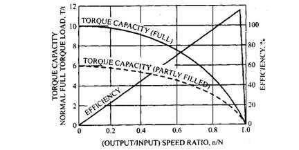
The fluid coupling efficiency is defined as the ratio of the power available at the turbine to the power supplied to the impeller. The difference between input and output power,, besides the power lost by fluid shock, friction and heat, is mainly due to the relative slip between the input and output members (Fig. 22.27). The percentage slip is defined as the ratio of the difference in input and output speeds, (N-n) to the input speed, N multiplied by 100.
![]()

Fig. 24.27. Relationship between torque capacity, efficiency and speed ratio for fluid coupling.
The percentage slip is greatly dependent on the engine speed and load condition of the output turbine (Fig. 24.28). A percentage of slip must always be present to create sufficient rate of vortex circulation necessary to impart energy from the impeller to the turbine. The maximum coupling efficiency is about 98% under light load high rotational speed conditions, and this is considerably reduced with increase, in turbine output or decrease in impeller speed. As the output torque demand increases, more slip occurs, which increases the vortex circulation velocity so that more kinetic energy is imparted to the output turbine member, thereby raising the torque capacity of the coupling.
The torque transmitting capacity of fluid coupling, T for a given slip varies as the fifth power of the impeller internal diameter, D and as the square of its speed, N.
![]()
Additionally, torque transmitting capacity also depends on the amount of fluid circulating between the impeller and turbine. Raising or lowering the fluid level in the coupling increases or decreases the torque, which can be transmitted to the turbine (Fig. 24.27). An additional feature to these types of coupling is that if the engine tends to stall due to overloading when the vehicle is accelerated from rest, the vortex circulation immediately slows down, preventing further torque transfer until the engine’s speed has recovered.
