24.8.
Multi-plate Clutch
A multi-plate clutch has more than one driven plate. Although this type of clutch has been widely used on cars up to about 1930, the several advantages of the single-plate clutch, specifically its ability to completely disengage the drive has caused a very rare use of a multi-plate unit as a main transmission clutch installed between the engine and gear box. However, a multi-plate type of clutch finds a use in automatic gearboxes. In these gearboxes, a number of clutches hold the various gear elements, and as the clutch diameter in these units is limited, a multi-plate clutch is suitable.
24.8.1.
Multi-plate Spring Type Clutch
Figure 24.16 illustrates the layout of a multi-plate spring type clutch, fitted on early motor cars. A cover, bolted to the flywheel, engages by means of slots with a series of lugs on the outer plates. These steel plates may be plain or fitted with cork or friction material inserts and act on inner plates, splined to a hub. Thrust springs push the plates together to form a drive.

Fig. 24.16. Multi-plate spring type clutch.
For the clutch disengagement, the end plate is withdrawn to compress the springs and release the other plates. In this arrangement it is difficult to ensure the disengagement of all plates. To overcome this problem the plates are either dished or fitted with small springs to push the plates apart.
Generally wet type clutch is used in automatic gearboxes, and is operated by a piston governed by hydraulic pressure. Sintered bronze plates of partially fusing powdered bronze or compressed paper are used in many designs. The porous surface of this plate traps the oil, to provide long life and smooth operation.
24.8.2.
Multi-plate Diaphragm Type Clutch
These clutches basically have drive and driven plates. The drive plates are not allowed to rotate independently by using interlocking lugs and slots, which do not permit relative rotational spin, but axial movement. The driven plates are mounted on the internally splined hubs, which splines on the gearbox spigot shaft (Fig. 24.17).
A dished annular disc forms the diaphragm spring, the inner portion of which is radially slotted and the outer ends are enlarged with a circular hole to prevent stress concentration during disengagement. These radial slots divide the disc into number of release levers. A
shouldered pivot post, riveted to the cover pressing locates the diaphragm spring in position. These rivets also hold a pair of fulcrum rings on either side of the diaphragm.

Fig. 24.17. Multi-plate diaphragm type clutch.
During operation, due to engagement and disengagement of the clutch, the diaphragm cone angle changes continuously as wear occurs. In order to accommodate the change, the diaphragm pivots and rolls about the fulcrum rings. During engagement of the clutch the diaphragm bears against the outer ring, and during disengagement the reaction load is taken by the inner ring. As the friction linings wear, the spring diaphragm becomes more dished so that a larger axial clamping load is applied initially. As the linings wear increases, the distance between the cover pressing and pressure plate become excessive, so that the axial thrust begins to decline.
24.8.3.
Multi-plate Hydraulically Operated Automatic Transmission Clutches
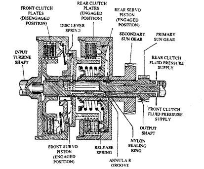
Multi-plate clutches are extensively used along with band brakes in epicyclic compound gear trains of automatic transmission system to lock different stages of the gearing or gear carriers together, so that a combination of gear ratios are available. These clutches contain a pack of annular discs or plates, and alternative plates are circumferentially grooved internally and externally to match up with the splines in the input and output drive members respectively (Fig. 24.18).
When these plates are pressed together, torque is transmitted from the input to the output members. These steel plates have either resented paper linings or with sintered bronze linings for transferring moderate or large torques respectively. The complete gear assembly is submerged in fluid, and hence the linings operate wet. These clutches are hydraulically operated by servo pistons either directly or indirectly through a lever disc spring, which multiplies the clamping load and also acts as a piston return spring. In this multi-plate clutch (Fig. 24.18) the hydraulic fluid is supplied under pressure through radial and axial passages in the output shaft. To transmit pressurized fluid from 0″>e member to another having relative angular movement,
the output shaft contain grooves on either side of all the radial supply passages. Square sectioned nylon sealing rings are pressed into these grooves to seal lengthwise portions of the shaft with their corresponding bore formed in the outer members.

Fig. 24.18. Multi-plate hydraulically actuated clutches.
When front clutch fluid supply system is pressurized, fluid passes to the front clutch piston chamber. The piston moves over to the right and, through the leverage of the disc spring, clamps the plates together. This causes locking of the primary sun gear to the input turbine shaft so that torque is transmitted from the input turbine shaft to the central output shaft and primary sun gear.
When rear clutch fluid supply system is pressurized, fluid from the front clutch piston chamber is transferred to the rear clutch piston chamber. This permits the servo piston to force directly against the end plate of the rear clutch multi-plate pack. The release spring is now compressed and the drive and driven plates are sandwiched together. As a result the secondary sun gear is locked to the input turbine shaft. Torque is now transmitted from the input turbine shaft to the secondary sun gear.
