The aims of this topic are:
1. To describe a variety of methods of dimensioning drawings.
2. To describe methods of adding text to drawings.
Introduction
The dimension style (My_style) has already been set in the acadiso.dwt template, which means that dimensions can be added to drawings using this dimension style.
The Dimension tools
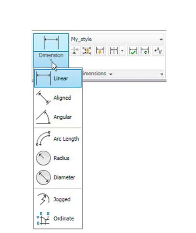
There are several ways in which the dimensions tools can be called. 1. From the Annotate/Dimensions panel (Fig. 6.1).
Fig. 6.1 Dimension tools in the Annotate/ Dimensions panel
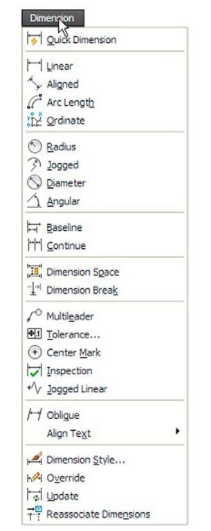
Fig. 6.2 Dimensions in the drop-down menu
2. Click Dimension in the menu bar. Dimension tools can be selected from the drop-down menu which appears (Fig. 6.2).
3. By entering an abbreviation for a dimension tool at the command line.
Some operators may well decide to use a combination of the three methods.
4. In the Classic AutoCAD workspace from the Dimension toolbar.
Note
In general, in this topic dimensions are shown in drawings in the Metrie style – mainly in millimetres, but some will be shown in Imperial style – in inches. To see how to set a drawing template for Imperial dimensioning see topic 4.
Adding dimensions using these tools
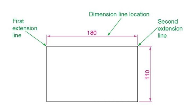
First example – Linear Dimension (Fig. 6.4)
1. Construct a rectangle 180 X 110 using the Polyline tool.
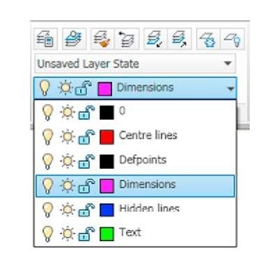
2. Make the Dimensions layer current from the Home/Layers panel (Fig. 6.3).
Fig. 6.3 The Home/Layers panel – making Dimensions layer current
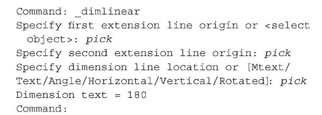
3. Click the Linear tool icon in the Annotate/Dimension panel (Fig. 6.1). The command line shows:
Fig. 6.4 shows the 180 dimension. Follow exactly the same procedure for the 110 dimension.
Fig. 6.4 First example – Linear dimension
Notes
1. If necessary use Osnaps to locate the extension line locations.
2. At the prompt:
Also allows the line being dimensioned to be picked.
3. The drop-down menu from the Line tool icon contains the following tool icons – Angular, Linear, Aligned, Arc Length, Radius, Diameter, Jog Line and Ordinate. Refer to Fig. 6.1 when working through the examples below. Note – when a tool is chosen from this menu, the icon in the panel changes to the selected tool icon.
Second example – Aligned Dimension (Fig. 6.5)
1. Construct the outline Fig. 6.5 using the Line tool.
Fig. 6.5 Second example – Aligned dimension
2. Make the Dimensions layer current (Home/Layers panel).
3. Left-click the Aligned tool icon (see Fig. 6.1) and dimension the outline. The prompts and replies are similar to the first example.
Third example – Radius Dimension (Fig. 6.6)
1. Construct the outline Fig. 6.5 using the Line and Fillet tools.
2. Make the Dimensions layer current (Home/Layers panel).
3. Left-click the Radius tool icon (see Fig. 6.1). The command line shows:
4. Continue dimensioning the outline as shown in Fig. 6.6.
Fig. 6.6 Third example – Radius dimension
Notes
1. At the prompt:
[Mtext/Text/Angle]:
If at (Text) is entered, another number can be entered, but remember if the dimension is a radius the letter R must be entered as a prefix to the new number.
2. If the response is a (Angle), and an angle number is entered the text for the dimension will appear at an angle.
3. If the response is m (Mtext) the Text Formatting dialog appears together with a box in which new text can be entered.
4. Dimensions added to a drawing using other tools from the Annotate/ Dimensions panel should be practised.
