The garage
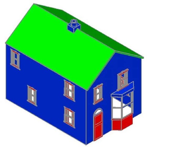
Fig. 16.17 First example – a Realistic view of the assembled walls, windows, bay, roof and chimney
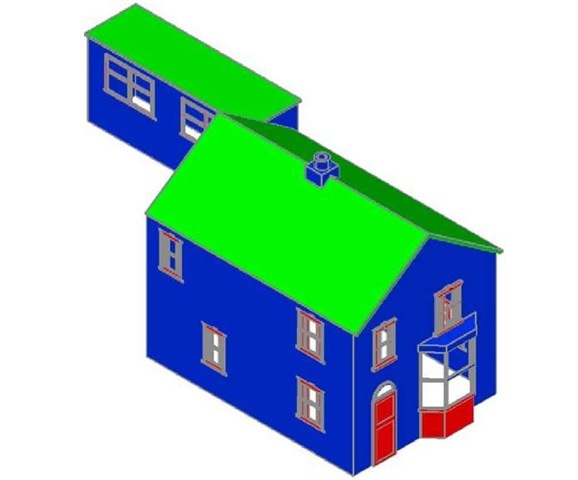
On layers Walls construct the walls and on layer Windows construct the windows. Fig. 16.19 is a Realistic visual style view of the 3D model as constructed so far.
Fig. 16.19 First example – Realistic view of the original house and garage
Second example – extension to 44 Ridgeway Road
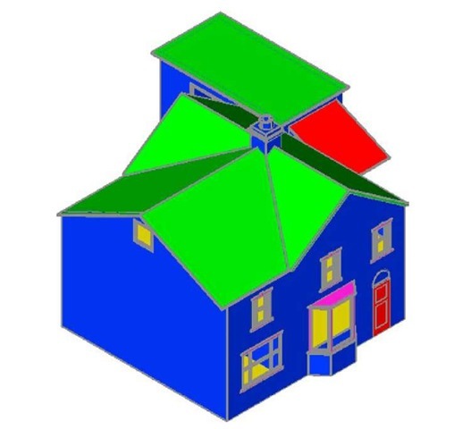
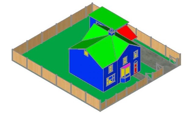
Working to a scale of 1:50 and taking dimensions from the drawing Figs 16.5 and 16.6 and in a manner similar to the method of constructing the 3D model of the original building, add the extension to the original building. Fig. 16.20 shows a Realistic visual style view of the resulting 3D model. In this 3D model floors have been added – a ground and a first storey floor constructed on a new layer Floors of colour yellow. Note the changes in the bay and front door.
Fig. 16.20 Second example – a Realistic view of the building with its extension
Third example – small building in fields
Working to a scale of 1:50 from the dimensions given in Fig. 16.21, construct a 3D model of the hut following the steps given below.
The walls are painted concrete and the roof is corrugated iron.
In the Layer Properties Manager dialog make the new levels as follows:
Walls – colour Blue Road – colour Red Roof – colour Red Windows – Magenta Fence – colour 8 Field – colour Green
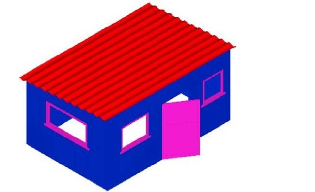
Following the methods used in the construction of the house in the first example, construct the walls, roof, windows and door of the small building in one of the fields. Fig. 16.22 shows a Realistic visual style view of a 3D model of the hut.
Constructing the fence, fields and road
1. Place the screen in a Four: Equal viewports setting.
2. Make the Garden layer current and in the Top viewport, construct an outline of the boundaries to the fields and to the building. Extrude the outline to a height of 0.5.
3. Make the Road layer current and in the Top viewport, construct an outline of the road and extrude the outline to a height of 0.5.
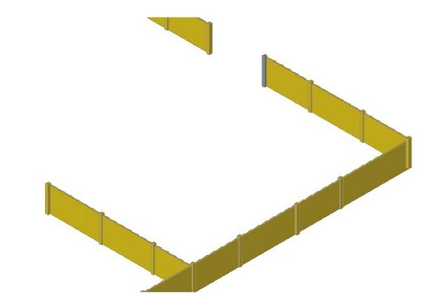
4. In the Front view, construct a single plank and a post of a fence and copy them a sufficient number of times to surround the four fields leaving gaps for the gates. With the Union tool form a union of all the posts and planks. Fig. 16.23 shows a part of the resulting fence in a Realistic visual style view in the Isometric viewport. With the Union tool form a union of all the planks and posts in the entire fence.
5. While still in the layer Fence, construct gates to the fields.
6. Make the Road layer current and construct an outline of the road. Extrude to a height of 0.5.
Fig. 16.21 Third example – front and end views of the hut
Fig. 16.22 Third example – a Realistic view of a 3D model of the hut
Fig. 16.23 Third example – part of the fence
Note
When constructing each of these features it is advisable to turn off those layers on which other features have been constructed.
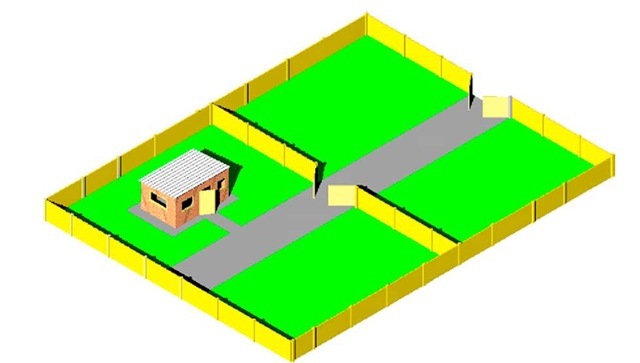
Fig. 16.24 shows a Conceptual view of the hut in the fields with the road, fence and gates.
Fig. 16.24 Third example – the completed 3D model
Completing the second example
Working in a manner similar to the method used when constructing the roads, garden and fences for the third example, add the paths, garden area and fences and gates to the building 44 Ridgeway Road with its extension. Fig. 16.24 is a Conceptual visual style view of the resulting 3D model.
Material attachments and rendering
Second example
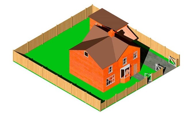
The following materials were attached to the various parts of the 3D model (Fig. 16.25). To attach the materials, all layers except the layer on which the objects to which the attachment of a particular material is being made are tuned off, allowing the material in question to be attached only to the elements to which each material is to be attached.
Fig. 16.25 Second example – the completed 3D model
Default: colour 7 Doors: Wood Hickory Fences: Wood – Spruce Floors: Wood – Hickory Garden: Green Gates: Wood – White Roofs: Brick – Herringbone Windows: Wood – White
The 3D model was then rendered with Output Size set to 1024 X 768 and Render Preset set to Presentation, with Sun Status turned on. The resulting rendering is shown in Fig. 16.26.
Third example
Fig. 16.27 shows the third example after attaching materials and rendering.
Fig. 16.26 Second example – a rendering after attaching materials
Fig. 16.27 Third example – 3D model after attaching materials and rendering
REVISION NOTES
1. There are a number of different types of building drawings – site plans, site layout plans, floor layouts, views, sectional views, detail drawings. AutoCAD 2011 is a suitable CAD program to use when constructing building drawings.
2. AutoCAD 2011 is a suitable CAD program for the construction of 3D models of buildings.
