8.1
The popular methods for sending Type- 1 FSK caller ID information are as follows:
1. Data transmission between first ring and second ring
2. Data transmission after alert but before actual first ring
3. Data transmission after an OSI
All these implementations use the same basic data transmission sequence with minor variations in FSK generation among ETSI and Telcordia implementations.

Figure 8.1. FSK Caller ID between two rings.
Case-1 Data Transmission Between First Ring and Second Ring. It is
commonly used in several countries such as North America, Canada, and so on. In this signaling method, FSK modulated data are sent during the silence periods between the first and the second ring. This on-hook service provides both number and name or only name as caller ID. The ring pattern is called cadence and varies with the country requirements. Data transmission shall occur during the first long silent period between ringing patterns as shown in Fig. 8.1. The first long silent period shall be of sufficient duration for transmitting FSK data. The initial application of the ringing provides an alert signal to the TE (phone) indicating the expected data transmission. The timing for FSK and ring pattern is shown in Fig. 8.1, and this should not take more than 2.9 seconds to transmit the entire data [ETSI ETS 300 659-1 (2001)]. Usually FSK data transmitted at 1200 bps takes a very short duration compared with the available 2.9 s.
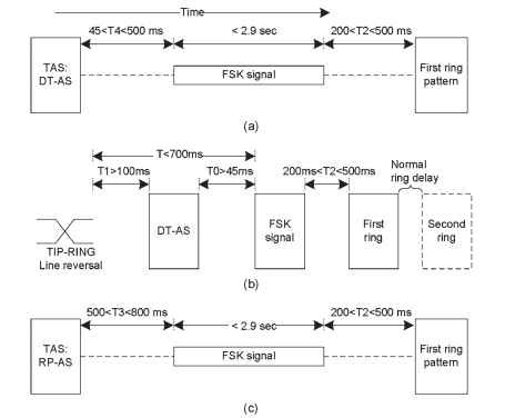
Case-2: Data Transmission After Alert but Before Actual First Ring. This type of alert-based caller ID is used in countries such as France and Japan. In this case, the data transmission occurs before the first ring. As shown in Fig. 8.2, an additional TE alerting signal (TAS) is sent before the data transmission [GR-31-CORE (2000)]. TAS signal characteristics differ between the different recommendations. In Fig. 8.2, timing intervals are marked as T, T0, T1, T2, T3, and T4, and these marking names may vary in country-specific documents. The three popular alerting signals used are dual-tone alerting signal (DT-AS), ringing pulse alerting signal (RP-AS), and line reversal followed by DT-AS
[ETSI ETS 300 659 - 1 (2001) , GR - 30 - CORE (1998) ]. Japan uses line reversal
followed by receiving terminal activation signal (CAR) as the alerting signal for on-hook caller ID display. The CAR signal is the receiving terminal activation signal or signal receiver seizing signal and is a short ring signal of 15-20 Hz. Refer to the NTT recommendation [URL (NTT-E)] for more details on Japan caller ID. To make caller ID work, any one of these alerting signals shall precede FSK modulation transmission within set time limits. The data transmission before the first ring using a dual-tone alerting signal is shown in Fig. 8.2(a). DT-AS shall precede FSK modulation transmission as 45 < T4 < 500 milliseconds (ms). The alerting signal DT-AS is also referred to as the CPE

Figure 8.2. Caller ID Data Transmission Before the First Ring Using (a) DT-AS, (b) DT-AS With Line Reversal, and (c) RP-AS.
alerting signal (CAS) in some places in the document. Both names convey the same alerting signal. The data transmission before the first ring using RP-AS is shown in Fig. 8.2(c). RP-AS shall precede FSK modulation transmission as 500 < T3 < 800 ms. The line reversal followed by DT-AS shall precede FSK modulation transmission by not less than 45 ms (T0 > 45 ms) as shown in Fig. 8.2(b). The total period between the line reversal and the start of FSK modulation is less than 700 ms marked as “T.” In all three methods, the application of ringing current shall start not less than 200 ms and not more than 500 ms (marked as T2) after FSK modulation transmission is stopped. The lower limits are required to enable TE to apply and remove appropriate impedance for data reception. In RP-AS, the time gap is more compared with DT-AS because of a high – voltage alert signal in RP – AS.
During caller ID, one of the three TAS signals is sent before data transmission. It varies by local PSTN standards. In this case, data transmission is associated with ringing and the FSK modulated caller ID message is followed by ring patterns. An appropriate idle condition can also be applied to the local
loop after FSK transmission. The important characteristics of DT-AS are listed here for the ETSI recommendation [ETSI ETS 300 659-1 (2001)].
Frequencies: 2130 and 2750Hz ± 0.5%
Duration: 100 ± 10 ms
Signal Level: -40dBV to -9dBV/tone
Signal purity: The total power of all extraneous signals in the voice band shall be at least 30dB lower than the power of signal fundamental frequency measured at the point of application.
Case-3: Data Transmission Alter an OSI. The OSI is the time duration when DC voltages are removed from TIP-RING lines. OSI is used as an alert to send messages and indications to the TE while the line is in the on-hook mode. This method is also known as data transmission without power ringing. In this case, the FSK modulated data are sent following a time period after OSI [GR-30-CORE (1998)]. No ringing follows the FSK data. The duration of the OSI shall be 150 to 300 ms, and the data transmission happens between 300 and 500ms after the end of the OSI. The default delay value is 500ms
[URL (Advent - CID1) ].
FSK CALLER ID ON PSTN (VoIP)
Next post: DTMF-BASED CALLER ID (VoIP)
Previous post: CALLER ID FEATURES IN VoIP
