8.3
Most caller ID signals use FSK-based implementation. Some countries like Finland, Denmark, Iceland, the Netherlands, India, Belgium, Sweden, Brazil, Taiwan, Saudi Arabia, and Uruguay make use of DTMF-based caller ID. In practice, many DTMF-caller-ID-supported phones are also made to work with FSK-based called ID. The phone displays are capable of supporting the numbers and alphabets. In the case of DTMF caller ID, only a number display is supported.
8.3.1
DMTF Caller ID on PSTN
For the transfer of display information over analog subscriber lines, 16-DTMF digits are used in DTMF-based caller ID. Except for these special display procedures, the normal signaling procedures and physical properties for analog subscriber lines also apply to DTMF caller ID [ETSI ETS 300 659-1 (2001)]). In case of an incoming call for a subscriber, the exchange shall seize the corresponding subscriber line for the terminating call. The line seizure may be indicated to the subscriber line by means of a polarity reversal of two lines of TIP-RING or through ring alert. In line reversal, the return to the idle polarity takes place after the information transfer phase. Two different modes for the data transmission are possible with DTMF—namely data transmission before the first ring and data transmission between the first and the second ring.
Data Transmission Before the First Ringing. In this mode, the data transmission shall occur before the beginning of the first ringing pattern. Two different procedures are possible to alert the TE namely subscriber line polarity reversal or ring alert. The subscriber line polarity is not applicable with ring alert. In both cases, the first ringing has to be within the time limits of 200 to 500 ms after the data transmission is stopped. In polarity reversal, the data transmission should not start sooner than 200 ms after the polarity reversal.

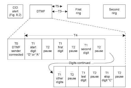
Figure 8.5. DTMF caller ID transmission.
The DTMF-based caller ID transmission method sends a series of DTMF digits before the first ringing cycle. In some implementations, alert signals are not used before data transmission in DTMF caller ID. In such cases, the central office provides a pause to connect the DTMF sender to the voice path [URL (Advent-CID2)]. As shown in Fig. 8.5, the calling number is sent after a “start” digit and ends when the “stop” digit is detected. Figure 8.5 represents the DTMF caller ID events before the first ring. The CID alert can be either ring pulse or polarity line reversal for DTMF- based caller ID. The transfer of number information is to be regarded as complete when the DTMF stop digit “C” is received or the ringing signal is detected. The following timing details of DTMF caller ID are marked in Fig. 8.5.
TO—Pause for the central office to connect the DTMF sender to the voice
path when no alert signal is preceded with DTMF transmission. TO is
between 50 ms and 400 ms. When line reversal is used as an alert, the delay from the end of the alert
signal to the start of the data transmission is between 200 ms and
500 ms.
T1—Duration of DTMF digit, >50ms varies by country.
T2—Inter-digit pause, >50ms varies by country.
T3—Delay from end of digits to start of first ring, 200 to 500 ms.
T4—Time required to send all DTMF digits, <3000ms.
T5—Return time to quiescent state after DTMF stop digit, <150ms.
Data Transmission Between First and Second Ring. In this mode, the data transmission shall occur during the first long silent period between two ringing patterns. The initial application of ringing is to provide an alert signal to the TE on possible data transmission. The data transmission should not start sooner than 500 ms after the first ringing pattern. At the end of caller ID data, the second ringing will start according to the normal ringing cadence. The timing of DTMF caller ID generation in the middle of the two rings will be similar to DTMF caller ID before the first ring of Fig. 8.5. In this method also, the second ringing has to be within the time limits of 200 to 500 ms after the data transmission is stopped. The caller ID number is sent after a “start” digit and ends with a “stop” digit. DTMF caller ID can display number and cannot display name.
Digits Data Coding. The DTMF transmission makes use of the 16-DTMF digit signals. Most telephones will use a keypad for the 0, 1, 2, 3, 4, 5, 6, 7, 8, 9, *, # digits. The DTMF-caller-ID-capable telephone can understand incoming A, B, C, and D digits for different interpretations. The interpretation of DTMF digits by the TE during caller ID is given here.
<A> DTMF code “A” is used as a start code for the calling party number.
The start and end codes are different for different countries. Refer to
country-specific PSTN recommendations for exact details on the DTMF
caller ID method and timing intervals. For example, the start code is digit
“A” for Brazil and “D” for Taiwan. <B> DTMF code “B” is used as a start code for the special information
concerning the nonavailability or restriction information of the calling
party number. It specifies the user category. <C> DTMF code “C” is used as an end code for the information
transfer.
<D> DTMF code “D” is used as a start code for the diverting party number in case of call diversion.
<0 to 9> DTMF codes “0 to 9″ are used as number digits of calling/diverting party or special information code value.
<*, #> DTMF digits *, and# are not used in DTMF caller ID.
DTMF digit details and tone generation are given in topic 7. The digits and pause periods vary depending on the country. It is required to refer to Q.24 [ITU-T- Q.24 (1998)] and to local country PSTN standards for the detailed specifications of DTMF digits and pause periods.
