Case Study: Finite Element Analysis of a Bicycle Frame
In the design of many modern devices and equipment, the finite element method has become an indispensable tool for the many successful products that we have come to use daily. In this case study, the analysis of a bicycle frame is carried out. Historically, intuition and trial-and-error in physical prototyping testing processes have played important roles in coming out with the evolution of today’s diamond-shaped bicycle frame, as shown in Figure 6.7. However, using such a physical trial-and-error design procedure is costly and time consuming, and has its limitations, especially when new materials are introduced and when new applications or demands are placed on the structure. Hence, there is the need to use the finite element tool to help the designer come up with reliable properties in the design to meet the demands expected by the consumers. Using the finite element method to perform a virtual prototyping instead of a physical prototyping can save lots of cost, time and effort.
Figure 6.7. Diamond-shaped bicycle frame.
There can be numerous factors to consider when it comes to designing a bicycle frame. For example, factors like the weight of the frame, the maximum load the frame can carry; the impact toughness of the frame, and so on. In a finite element analysis, one would require information on the material properties, the boundary conditions and the loading conditions. The loading conditions on a bicycle can be extremely complex, especially when a rider is riding a bicycle and going through different terrain. In this case study we consider a loading condition of a horizontal impact applied to the bicycle, simulating the effect of a low speed, head-on collision into a wall or curb. This case is one of the physical tests that manufacturers have to comply with before a bicycle design is approved.
Modelling
The bicycle frame to be modelled is made of aluminium, whose properties are shown in Table 6.1. The bicycle frame is meshed by two-nodal ‘beam elements’ in ABAQUS. Note that in ABAQUS, as well as many other software, a general beam element in space is basically the same as the frame element developed in this topic. The ‘beam element’ in space offered by ABAQUS has the same DOFs as the frame element in this topic, that is, three translational DOFs and three rotational DOFs.
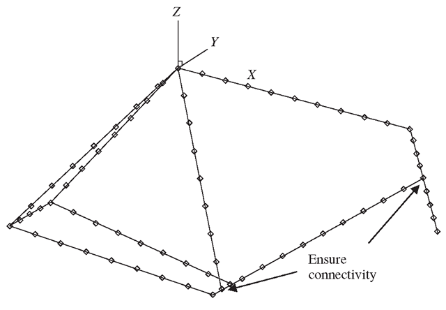
Altogether, 74 elements (71 nodes) are used in the skeletal model of the bicycle frame, as shown in Figure 6.8. Note that like all finite element meshes, connectivity at the nodes is very important. It is important to make sure that at the joints, there is connectivity between the elements. No node should be left unattached to another element unless the node happens to be at the end of a structure.
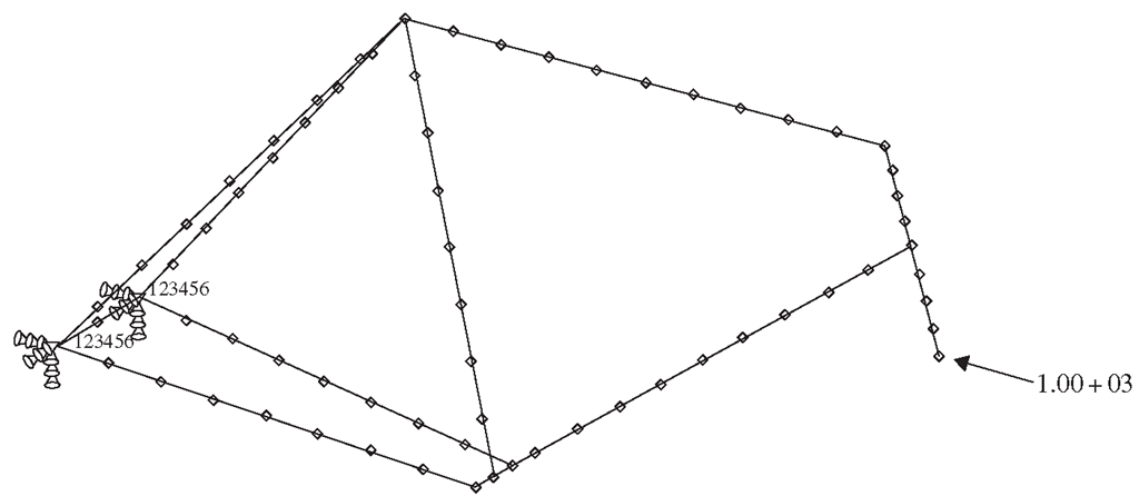
To model the horizontal impact, the two nodes at the rear dropouts are constrained from any displacements and a horizontal force of 1000 N is applied to the front dropout. The forces and constraints are shown in Figure 6.9.
Abaqus Input File
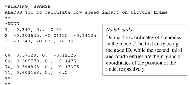
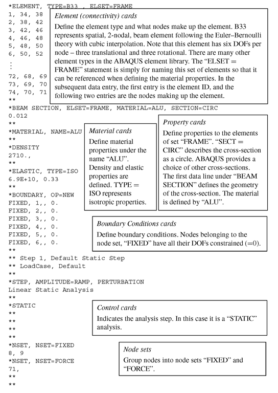
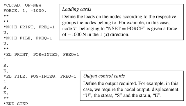
The ABAQUS input file for the above-described finite element model is shown below. The text boxes to the right of the input file are not part of the file, but explain what the sections of the file mean.
Table 6.1. Material properties of aluminium
|
Young’s modulus, E GPa |
Poisson’s ratio, ν |
|
69.0 |
0.33 |
Figure 6.8. Finite element mesh of a bicycle frame.
Figure 6.9. Loadings and boundary conditions on the bicycle frame.
In fact, most ABAQUS input files have similar formats, only the information provided may be different depending on the problem required to solve.
Solution Processes
The nodal and element cards provide information on the dimensions, position of nodes and the connectivity of the elements. As discussed, these parameters play important roles in the formation of the element stiffness and mass matrices. Note that in the element cards, the element type specified is B33 which represents a general ‘beam element’ in space with two nodes following the Euler-Bernoulli beam theory for its transverse displacement field. In ABAQUS, this would be exactly the same as the frame element developed in this topic, since the degrees of freedom also include the axial displacement component. ABAQUS, like most other software, does not have a pure beam element consisting of only the transverse displacement field. This is because not many real structures are a true beam structure without the axial displacement components. Hence, readers should not be confused by the use of beam elements in this case.
Next, the material properties and the cross-sectional geometry and dimensions are provided in the material cards and properties cards, respectively. As can be seen in Eqs. (6.4) and (6.5), the material properties as well as the moment of area is required to compute the stiffness and mass matrices. It is interesting to note that most of the information provided goes into forming the finite element matrices. In fact, that is the basic idea when it comes to applying the finite element method: to form the finite element matrix equation and solve the equation to obtain the required field variables.
The next card would be the definition of the boundary conditions. In this case, the rear dropouts that are represented by nodes 8 and 9 and grouped as a node set, ‘FIXED’, are constrained in all DOFs. Recall that in this case, since each node has six DOFs, we can actually reduce the size of the matrix here by eliminating 12 rows and columns each.For the loads, it is given as a concentrated force of -1000 N at node 71 in the X direction. This would be reflected in the force vector, Eq. (6.42).
The control cards control the type of analysis to be performed, which in this case is a static analysis. In static analyses, the static equation KD = F is solved for D, which is a vector of the displacements and rotations of the nodes in the model. The method used is usually algorithms like the Gauss elimination method, which is mentioned in Section 3.5.
The last part of the input file would consist of the output control cards, which specify the type of output requested. In this case, the nodal displacement and rotation components (U) and the elemental stress (S) and strain (E) components are specified. With the input file written, one can then invoke ABAQUS to execute the analysis.
Results and Discussion
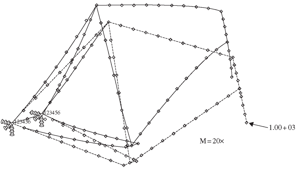
Using the above input file, the finite element equation is solved and a deformation plot showing how the frame actually deforms under the specified loading is shown in Figure 6.10. The magnitude of the deformation is actually magnified 20 x as the true deformation is much too small for viewing purposes. Such deformation plots, or the results containing the displacements of the nodes, are useful to a designer since he or she will then be able to visualize the way in which the frame will deform under specific conditions. Furthermore, knowing the magnitude of deformation also helps to gauge aspects of the frame in the design, as consumers would not want a bicycle which could not be ridden once one accidentally hits a wall or curb at slow speed.
Figure 6.10. Deformation plot of bicycle frame.
Figure 6.11. Stresses in the bicycle frame.
The other more important result that could be obtained from this case study would be the stresses that incur with this particular loading condition. Figure 6.11 shows the average axial stresses along the centroid of the aluminum beam members. It should be noted that it is possible to obtain stresses on different sections of the cross-section, for example, the upper or lower surface along the circumference of a circular cross-section. These stresses are useful for testing whether the bicycle frame will fail under the applied loads. If these stresses are smaller than the yield stress or the design stress of the material, then it can be safely concluded that there is a high chance that the material will not fail or undergo plastic deformation. It is important that the deformations remain elastic, that is, it will return to the original shape upon removal of the applied load.
Hence, it can be seen how the finite element method can aid the design engineer when it comes to designing a product. It would be disastrous if a new design of an engineering system is mass-produced without going through any sort of analysis to check its reliability.

