Moments and Shear Forces
Because the loading on the beam is in the transverse direction, there will be moments and corresponding shear forces imposed on the cross-sectional plane of the beam. On the other hand, bending of the beam can also be achieved if pure moments are applied instead of transverse loading. Figure 2.11 shows a small representative cell of length dx of the beam. The beam cell is subjected to external force, fz, moment, M, shear force, Q, and inertial force, pAw, where ρ is the density of the material and A is the area of the cross-section.
Figure 2.11. Isolated beam cell of length dx. Moments and shear forces are obtained by integration of stresses over the cross-section of the beam.
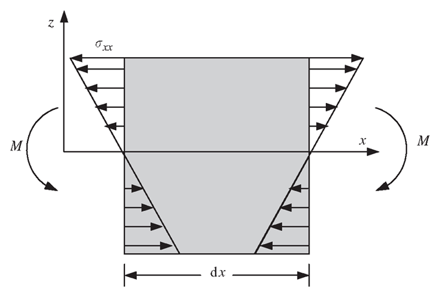
Figure 2.12. Normal stress that results in moment.
The moment on the cross-section at x results from the distributed normal stress σχχ, as shown in Figure 2.12. The normal stress can be calculated by substituting Eq. (2.47) into Eq. (2.49):
It can be seen from the above equation that the normal stress σχχ varies linearly in the vertical direction on the cross-section of the beam. The moments resulting from the normal stress on the cross-section can be calculated by the following integration over the area of the cross-section:
where I is the second moment of area (or moment of inertia) of the cross-section with respect to the y-axis, which can be calculated for a given shape of the cross-section using the following equation:
We now consider the force equilibrium of the small beam cell in the z direction
or
We would also need to consider the moment equilibrium of the small beam cell with respect to any point at the right surface of the cell,
Neglecting the second order small term containing (dx)2 leads to
And finally, substituting Eq. (2.51) into Eq. (2.56) gives
Equations (2.56) and (2.57) give the relationship between the moments and shear forces in a beam with the deflection of the Euler-Bernoulli beam.
Dynamic Equilibrium Equations
The dynamic equilibrium equation for beams can be obtained simply by substituting Eq. (2.57) into Eq. (2.54):
The static equilibrium equation for beams can be obtained similarly by dropping the dynamic term in Eq. (2.58):
Equations For Plates
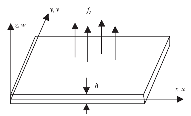
The wings of an aircraft can sometimes be considered as a plate structure carrying transverse loads in the form of engines or other components, as shown in Figure 2.13. A plate possesses a geometrically similar dimensional characteristic as a 2D solid, as shown in Figure 2.14. The difference is that the forces applied on a plate are in the direction perpendicular to the plane of the plate. A plate can also be viewed as a 2D analogy of a beam. Therefore, a plate experiences bending resulting in deflection w in the z direction, which is a function of x and y.
Stress and Strain
Similar to beams, there are several theories for analysing deflection in plates. These theories can also be basically divided into two major categories: a theory for thin plates and a theory for thick plates. This topic addresses thin plate theory, often called Classical Plate Theory (CPT), or the Kirchhoffplate theory, as well as the first order shear deformation theory for thick plates known as the Reissner-Mindlin plate theory (Reissner, 1945; Mindin, 1951). However, pure plate elements are usually not available in most commercial finite element packages, since most people would use the more general shell elements, which will be discussed in later topics.
Figure 2.13. An aircraft wing can be idealized as a plate structure.
Figure 2.14. A plate subjected to transverse load that results in bending deformation.
Furthermore, it is found that the CPT is not very practical for many situations, since shear deformation should not be neglected for most structures. Hence, in this topic, only equations of plate elements based on the Reissner-Mindlin plate theory will be formulated.Nevertheless, the CPT will also be briefed in this topic for completeness of this introduction to mechanics for solids and structures.
The CPT assumes that normals to the middle (neutral) plane of the undeformed plate remain straight and normal to the middle plane during deformation or bending. This assumption results in
Secondly, the displacements parallel to the undeformed middle plane, u and v, at a distance z from the centroidal axis can be expressed by
where w is the deflection of the middle plane of the plate in the z direction. The relationship between the components of strain and the deflection can be given by
or in the matrix form
where ε is the vector of in-plane strains defined by Eq. (2.25), and L is the differential operator matrix given by
Constitutive Equations
The original Hooke’s law is applicable for plates:
where c has the same form for 2D solids defined by Eq. (2.31), the plane stress case, since σζζ is assumed to be zero.
Moments and Shear Forces
Figure 2.15 shows a small representative cell of dx x dy from a plate of thickness h. The plate cell is subjected to external force fz, and inertial force phW, where ρ is the density of the material. Figure 2.16 shows the moments Mx,My, Mz and Mxy, and shear forces Qx and Qy present. The moments and shear forces result from the distributed normal and shear stresses σχχ, σyy and σxy, shown in Figure 2.15. The stresses can be obtained by substituting Eq. (2.66) into Eq. (2.68)
Figure 2.15. Stresses on an isolated plate cell. Integration of these stresses results in corresponding moments and shear forces.
Figure 2.16. Shear forces and moments on an isolated plate cell of dxx dy. The equilibrium system equations are established based on this state of forces and moments.
It can be seen from the above equation that the normal stresses vary linearly in the vertical direction on the cross-sections of the plate. The moments on the cross-section can be calculated in a similar way as for beams by the following integration:
Consider first the equilibrium of the small plate cell in the z direction, and note that
or
Consider then the moment equilibrium of the plate cell with respect to the x-axis, and neglecting the second order small term, leads to a formula for shear force![]()
Finally, consider the moment equilibrium of the plate cell with respect to the y-axis, and neglecting the second order small term, gives
in which we implied that
Dynamic Equilibrium Equations
To obtain the dynamic equilibrium equation for plates, we first substitute Eq. (2.70) into Eqs. (2.73) and (2.74), after which Qx and Qy are substituted into Eq. (2.72):
where![tmp4454-123_thumb[2][2] tmp4454-123_thumb[2][2]](http://what-when-how.com/wp-content/uploads/2012/06/tmp4454123_thumb22_thumb.png) is the bending stiffness of the plate. The static equilibrium equation for plates can again be obtained by dropping the dynamic term in Eq. (2.75):
is the bending stiffness of the plate. The static equilibrium equation for plates can again be obtained by dropping the dynamic term in Eq. (2.75):
Reissner-Mindlin Plate (Reissner, 1945; Mindlin, 1951)
The Reissner-Mindlin plate theory is applied for thick plates, where the shear deformation and rotary inertia effects are included. The Reissner-Mindlin theory does not require the cross-section to be perpendicular to the axial axes after deformation, as shown in Figure 2.17. Therefore,![]() The displacements parallel to the undeformed middle surface, u and v, at a distance z from the centroidal axis can be expressed by
The displacements parallel to the undeformed middle surface, u and v, at a distance z from the centroidal axis can be expressed by
where θχ and θy are, respectively, the rotations about the x and y axes of lines normal to the middle plane before deformation.
Figure 2.17. Shear deformation in a Mindlin plate. The rotations of the cross-sections are treated as independent variables.
The in-plane strains defined by Eq. (2.25) are given by
where
Using Eq. (2.4), the transverse shear strains sxz and syz can be obtained as
Note that if the transverse shear strains are negligible, the above equation will lead to
and Eq. (2.79) becomes Eq. (2.66) of the CPT. The transverse average shear stress τ relates to the transverse shear strain in the form
where G is the shear modulus, and κ is a constant that is usually taken to be![tmp4454-135_thumb[2][2] tmp4454-135_thumb[2][2]](http://what-when-how.com/wp-content/uploads/2012/06/tmp4454135_thumb22_thumb.png)
The equilibrium equations for a Reissner-Mindlin plate can also be similarly obtained as that of a thin plate. Equilibrium of forces and moments can be carried out but this time taking into account the transverse shear stress and rotary inertia. For the purpose of this topic, the above concepts for the Reissner-Mindlin plate will be sufficient and the equilibrium equations will not be shown here.
Remarks
Having shown how the equilibrium equations for various types of geometrical structures are obtained, it can be noted that all the equilibrium equations are just special cases of the general equilibrium equation for 3D solids. The use of proper assumptions and theories can lead to a dimension reduction, and hence simplify the problem. These kinds of simplification can significantly reduce the size of finite element models.


![tmp4454-92_thumb[2][2] tmp4454-92_thumb[2][2]](http://what-when-how.com/wp-content/uploads/2012/06/tmp445492_thumb22_thumb.png)
![tmp4454-93_thumb[2][2] tmp4454-93_thumb[2][2]](http://what-when-how.com/wp-content/uploads/2012/06/tmp445493_thumb22_thumb.png)
![tmp4454-95_thumb[2][2] tmp4454-95_thumb[2][2]](http://what-when-how.com/wp-content/uploads/2012/06/tmp445495_thumb22_thumb.png)
![tmp4454-97_thumb[2][2] tmp4454-97_thumb[2][2]](http://what-when-how.com/wp-content/uploads/2012/06/tmp445497_thumb22_thumb.png)
![tmp4454-98_thumb[2][2] tmp4454-98_thumb[2][2]](http://what-when-how.com/wp-content/uploads/2012/06/tmp445498_thumb22_thumb.png)
![tmp4454-99_thumb[2][2] tmp4454-99_thumb[2][2]](http://what-when-how.com/wp-content/uploads/2012/06/tmp445499_thumb22_thumb.png)
![tmp4454-100_thumb[2][2] tmp4454-100_thumb[2][2]](http://what-when-how.com/wp-content/uploads/2012/06/tmp4454100_thumb22_thumb.png)


![tmp4454-103_thumb[2][2] tmp4454-103_thumb[2][2]](http://what-when-how.com/wp-content/uploads/2012/06/tmp4454103_thumb22_thumb.png)
![tmp4454-104_thumb[2][2] tmp4454-104_thumb[2][2]](http://what-when-how.com/wp-content/uploads/2012/06/tmp4454104_thumb22_thumb.png)
![tmp4454-105_thumb[2][2] tmp4454-105_thumb[2][2]](http://what-when-how.com/wp-content/uploads/2012/06/tmp4454105_thumb22_thumb.png)
![tmp4454-107_thumb[2][2] tmp4454-107_thumb[2][2]](http://what-when-how.com/wp-content/uploads/2012/06/tmp4454107_thumb22_thumb.png)


![tmp4454-112_thumb[2][2] tmp4454-112_thumb[2][2]](http://what-when-how.com/wp-content/uploads/2012/06/tmp4454112_thumb22_thumb.png)
![tmp4454-115_thumb[2][2] tmp4454-115_thumb[2][2]](http://what-when-how.com/wp-content/uploads/2012/06/tmp4454115_thumb22_thumb.png)
![tmp4454-116_thumb[2][2] tmp4454-116_thumb[2][2]](http://what-when-how.com/wp-content/uploads/2012/06/tmp4454116_thumb22_thumb.png)
![tmp4454-119_thumb[2][2] tmp4454-119_thumb[2][2]](http://what-when-how.com/wp-content/uploads/2012/06/tmp4454119_thumb22_thumb.png)
![tmp4454-120_thumb[2][2] tmp4454-120_thumb[2][2]](http://what-when-how.com/wp-content/uploads/2012/06/tmp4454120_thumb22_thumb.png)
![tmp4454-121_thumb[2][2] tmp4454-121_thumb[2][2]](http://what-when-how.com/wp-content/uploads/2012/06/tmp4454121_thumb22_thumb.png)
![tmp4454-122_thumb[2][2] tmp4454-122_thumb[2][2]](http://what-when-how.com/wp-content/uploads/2012/06/tmp4454122_thumb22_thumb.png)
![tmp4454-125_thumb[2][2] tmp4454-125_thumb[2][2]](http://what-when-how.com/wp-content/uploads/2012/06/tmp4454125_thumb22_thumb.png)
![tmp4454-128_thumb[2][2] tmp4454-128_thumb[2][2]](http://what-when-how.com/wp-content/uploads/2012/06/tmp4454128_thumb22_thumb.png)

![tmp4454-131_thumb[2][2] tmp4454-131_thumb[2][2]](http://what-when-how.com/wp-content/uploads/2012/06/tmp4454131_thumb22_thumb.png)
![tmp4454-132_thumb[2][2] tmp4454-132_thumb[2][2]](http://what-when-how.com/wp-content/uploads/2012/06/tmp4454132_thumb22_thumb.png)
![tmp4454-133_thumb[2][2] tmp4454-133_thumb[2][2]](http://what-when-how.com/wp-content/uploads/2012/06/tmp4454133_thumb22_thumb.png)
![tmp4454-134_thumb[2][2] tmp4454-134_thumb[2][2]](http://what-when-how.com/wp-content/uploads/2012/06/tmp4454134_thumb22_thumb.png)
