Equations in Global Coordinate System
Having known the element matrices in the local coordinate system, the next thing to do is to transform the element matrices into the global coordinate system to account for the differences in orientation of all the local coordinate systems that are attached on individual frame members.
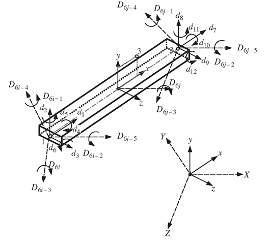
Assume that the local nodes 1 and 2 of the element correspond to global nodes i and j, respectively. The displacement at a local node should have three translational components in the x, y and z directions, and three rotational components with respect to the x, y and z-axes. They are numbered sequentially by d1-d12 corresponding to the physical deformations as defined by Eq. (6.16). The displacement at a global node should also have three translational components in the X, Y and Z directions, and three rotational components with respect to the X, Y and Z axes. They are numbered sequentially by![tmpabe4-42_thumb[2] tmpabe4-42_thumb[2]](http://what-when-how.com/wp-content/uploads/2012/06/tmpabe442_thumb2_thumb.png) for the ith node, as shown in Figure 6.5. The same sign convention applies to node j. The coordinate transformation gives the relationship between the displacement vector de based on the local coordinate system and the displacement vector De for the same element but based on the global coordinate system:
for the ith node, as shown in Figure 6.5. The same sign convention applies to node j. The coordinate transformation gives the relationship between the displacement vector de based on the local coordinate system and the displacement vector De for the same element but based on the global coordinate system:
Figure 6.5. Coordinate transformation for a frame element in space.
where
and T is the transformation matrix for the truss element given by
in which
where![tmpabe4-49_thumb[2] tmpabe4-49_thumb[2]](http://what-when-how.com/wp-content/uploads/2012/06/tmpabe449_thumb2_thumb.png) are direction cosines defined by
are direction cosines defined by
To define these direction cosines, the position and the three-dimensional orientation of the frame element have to be defined first. With nodes 1 and 2, the location of the element is fixed on the local coordinate frame, and the orientation of the element has also been fixed in the x direction. However, the local coordinate frame can still rotate about the axis of the beam. One more additional point in the local coordinate has to be defined. This point can be chosen anywhere in the local x-y plane, but not on the x-axis. Therefore, node 3 is chosen, as shown in Figure 6.6.
The position vectors![tmpabe4-52_thumb[2] tmpabe4-52_thumb[2]](http://what-when-how.com/wp-content/uploads/2012/06/tmpabe452_thumb2_thumb.png) can be expressed as
can be expressed as
where![]() are the coordinates for node k, and
are the coordinates for node k, and![tmpabe4-57_thumb[2] tmpabe4-57_thumb[2]](http://what-when-how.com/wp-content/uploads/2012/06/tmpabe457_thumb2_thumb.png) are unit vectors along the X, Y and Z axes.
are unit vectors along the X, Y and Z axes.
Figure 6.6. Vectors for defining the location and three-dimensional orientation of the frame element in space.
We now define
Vectors![tmpabe4-61_thumb[2] tmpabe4-61_thumb[2]](http://what-when-how.com/wp-content/uploads/2012/06/tmpabe461_thumb2_thumb.png) can thus be obtained using Eqs. (6.25) to (6.28) as follows:
can thus be obtained using Eqs. (6.25) to (6.28) as follows:
The length of the frame element can be obtained by
The unit vector along the x-axis can thus be expressed as
Therefore, the direction cosines in the x direction are given as
From Figure 6.6, it can be seen that the direction of the z-axis can be defined by the cross product of vectors![tmpabe4-67_thumb[2] tmpabe4-67_thumb[2]](http://what-when-how.com/wp-content/uploads/2012/06/tmpabe467_thumb2_thumb.png) Hence, the unit vector along the z-axis can be expressed as
Hence, the unit vector along the z-axis can be expressed as
Substituting Eqs. (6.29) and (6.30) into the above equation,
where
Using Eq. (6.35), it is found that
Since the y-axis is perpendicular to both the x-axis and the z-axis, the unit vector along the y-axis can be obtained by cross product,
which gives
in which![]() have been obtained using Eqs. (6.33) and (6.37).
have been obtained using Eqs. (6.33) and (6.37).
Using the transformation matrix, T, the matrices for space frame elements in the global coordinate system can be obtained as
Remarks
In the formulation of the matrices for the frame element in this topic, the superposition of the truss element and the beam element has been used. This technique assumes that the axial effects are not coupled with the bending effects in the element. What this means simply is that the axial forces applied on the element will not result in any bending deformation, and the bending forces will not result in any axial deformation. Frame elements can also be used for frame structures with curved members. In such cases, the coupling effects can exist even in the elemental level. Therefore, depending on the curvature of the member, the meshing of the structure can be very important. For example, if the curvature is very large resulting in a significant coupling effect, a finer mesh is required to provide the necessary accuracy.
In practical structures, it is very rare to have beam structures subjected to purely transverse loading. Most skeletal structures are either trusses or frames that carry both axial and transverse loads.Therefore, in most commercial software packages, including ABAQUS, the frame element is just known generally as the beam element.
For thick or deep beams of a large thickness to pan ratio, corresponding beam theories should be used to develop thick beam elements.Most commercial software packages also offer thick beam elements, and the use of these elements is much the same as the thin beam elements.

![tmpabe4-45_thumb[2] tmpabe4-45_thumb[2]](http://what-when-how.com/wp-content/uploads/2012/06/tmpabe445_thumb2_thumb.png)
![tmpabe4-46_thumb[2] tmpabe4-46_thumb[2]](http://what-when-how.com/wp-content/uploads/2012/06/tmpabe446_thumb2_thumb.png)
![tmpabe4-47_thumb[2] tmpabe4-47_thumb[2]](http://what-when-how.com/wp-content/uploads/2012/06/tmpabe447_thumb2_thumb.png)
![tmpabe4-48_thumb[2] tmpabe4-48_thumb[2]](http://what-when-how.com/wp-content/uploads/2012/06/tmpabe448_thumb2_thumb.png)
![tmpabe4-51_thumb[2] tmpabe4-51_thumb[2]](http://what-when-how.com/wp-content/uploads/2012/06/tmpabe451_thumb2_thumb.png)
![tmpabe4-54_thumb[2] tmpabe4-54_thumb[2]](http://what-when-how.com/wp-content/uploads/2012/06/tmpabe454_thumb2_thumb.png)

![tmpabe4-60_thumb[2] tmpabe4-60_thumb[2]](http://what-when-how.com/wp-content/uploads/2012/06/tmpabe460_thumb2_thumb.png)
![tmpabe4-63_thumb[2] tmpabe4-63_thumb[2]](http://what-when-how.com/wp-content/uploads/2012/06/tmpabe463_thumb2_thumb.png)
![tmpabe4-64_thumb[2] tmpabe4-64_thumb[2]](http://what-when-how.com/wp-content/uploads/2012/06/tmpabe464_thumb2_thumb.png)
![tmpabe4-65_thumb[2] tmpabe4-65_thumb[2]](http://what-when-how.com/wp-content/uploads/2012/06/tmpabe465_thumb2_thumb.png)
![tmpabe4-66_thumb[2] tmpabe4-66_thumb[2]](http://what-when-how.com/wp-content/uploads/2012/06/tmpabe466_thumb2_thumb.png)
![tmpabe4-69_thumb[2] tmpabe4-69_thumb[2]](http://what-when-how.com/wp-content/uploads/2012/06/tmpabe469_thumb2_thumb.png)
![tmpabe4-72_thumb[2] tmpabe4-72_thumb[2]](http://what-when-how.com/wp-content/uploads/2012/06/tmpabe472_thumb2_thumb.png)
![tmpabe4-74_thumb[2] tmpabe4-74_thumb[2]](http://what-when-how.com/wp-content/uploads/2012/06/tmpabe474_thumb2_thumb.png)
![tmpabe4-77_thumb[2] tmpabe4-77_thumb[2]](http://what-when-how.com/wp-content/uploads/2012/06/tmpabe477_thumb2_thumb.png)
