Introduction
The Patil frame is designed to allow surgeons to measure coordinates directly on the scanner screen and obtain intraoperative images to confirm accuracy of the procedure. It is a center of the arc system and modification of the original Patil frame [1].
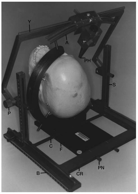
The frame (Fig. 1) consists of a fiducial plate, a head-ring, a base frame, two side stanchions, two pivot blocks, a yoke, an arc, several probe holders (for probes of different diameters) and several head pins (of different lengths). The fiducial plate is made of acetyl resin, the head holder of poly-carbon, the head pins of titanium, and the remainder of the frame of anodized aluminum. The inferior surface of the fiducial plate has two grooves that serve as fiducial markers for computed tomography (CT) images: an outer groove that is parallel to and along the left margin of the plate, and an inner groove that is 45° to the outer groove and meets the outer groove at its caudal end. For magnetic resonance (MR) images, two tubes filled with paramagnetic solution (that serve as fiducial markers) are inserted in these grooves. The superior surface of the fiducial plate has attachments for the head ring and the base frame. The attachment for the head-ring is an elevated bracket.
Figure 1 The Patil stereotactic system. A, arc; PH, probe holder; Y, yoke; S, side stanchion; P, pivot block; B, base frame; C, caudal cross bar; CR, cranial cross bar; PN, pin connecting the cranial cross bar to the fiducial plate; F, fiducial plate.
The head ring, which is C-shaped, is inserted into this bracket and secured by means of a screw. The base frame is attached to the fiducial plate by inserting its caudal crossbar into the transverse groove on the superior surface of the fiducial plate, and by means of two pins that connect the cranial crossbar of the base frame and the fiducial plate. The side stanchions are mounted on the sidebars of the base frame, the pivot blocks on the side stanchions, the yoke on the pivot blocks, and the arc on the yoke. The arc has a probe carrier into which the probe holder is inserted. The latter can slide along the length of the probe holder to change the depth of the probe. The system is arc centered and the radius of the arc is 21 cm. A 21-cm length probe is, therefore, used with this system. Zero for the Z coordinate (craniocaudal distance) is at a point where the two fiducial markers meet, zero for the Y coordinate (anterior-posterior distance) is the horizontal plane in which the two fiducial markers are located, and zero for the X coordinate (lateral distance) is in the vertical plane in which the left (outer) fiducial marker is located. Because the inner fiducial markers is at 45° to the outer fiducial marker, the distance between the two markers at any given point is equal to the perpendicular distance of that point from the meeting point of the markers.
Method
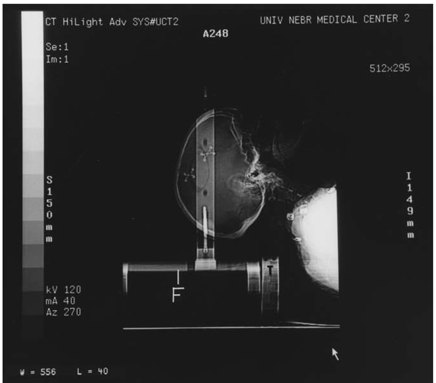
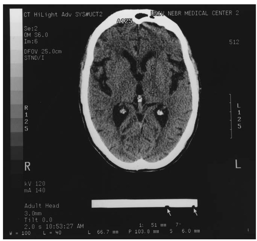
The procedure can be performed in the operating room or on the CT table. The head holder is attached to the fiducial plate, which in turn is attached perfectly horizontal and parallel to the CT table by means of a CT table interface. The head is fixed in the head holder by three head pins (Fig. 2). Special care is taken to avoid attaching the head pins in the plane in which the target is present. The CT table is set to a height at which the head and fiducial markers are both visible on a single CT image. The table height is noted and used for subsequent procedures. Serial CT images 3 mm in thickness at 1.5-mm intervals with a 25-cm field of view are then obtained through the area of interest. The gantry is not tilted. The image with the target is chosen (Fig. 3). Using the cursor of the scanner and measure distance mode, the angle of the coronal trajectory with the vertical is measured. Then the Y (perpendicular distance of the target from the horizontal plane of the fiducial markers), X (perpendicular distance of the target from the outer fiducial marker), and Z (distance between the two fiducial marker) coordinates are measured (Fig. 4). The base frame is then connected to the fiducial plate, the coordinates are adjusted, and the probe holder on the arc and the yoke on the pivot block are set at angles to allow safe passage of the probe. These angles can be chosen based on surface anatomy or on reconstructed images. A burr-hole is then made, a probe is placed at the target, and intraoperative scans are obtained to confirm accuracy of probe placement. When the procedure is performed in the operating room (e.g., during stereotactic craniotomy), after the coordinates are obtained, the fiducial plate is detached from the CT table and attached to the operating table interface.
Figure 2 Scout image with the patient’s head in the head holder
During MR stereotaxis, MR fiducial markers are inserted into the fiducial grooves. Scans are obtained using the head coil of the MR scanner with the head holder and the fiducial plate attached to the patient’s head. Coordinates are measured using the same technique used for CT images.
During linear accelerator radiosurgery, after coordinates are measured, the fiducial plate (with the head holder and the patient’s head in it) is attached to the Linac table. The remainder of the frame is then attached to the fiducial plate, the coordinates are adjusted, the probe holder is set at zero position on the arc and the yoke is set perfectly vertical. The vertical positioning light is then aligned with the hole in the probe holder, and the side positioning lights are aligned with the center of the pivot blocks. This sets the target at the isocenter. The base frame (together with the components attached to it) are detached from the fiducial plate, and irradiation is started.
Figure 3 Computed tomographic image shows the thalamic target for deep brain stimulator (DBS) implant marked by a cursor. The coronal trajectory is marked by the line. The angle of this trajectory is displayed at the bottom of the image. The arrows mark the inner and outer (left) fiducial markers.
Indications For Using The System
The system can be used for functional neurosurgical procedures including implantation of deep brain stimulators, biopsy of intracranial lesions, brachytherapy, aspiration of cysts, aspiration of brain abscesses, stereotactic craniotomies, and radiosurgery.
Figure 4 Computed tomographic image with coordinate measurements. The two arrows mark the fiducial markers. 1-Y coordinate (perpendicular distance from the target to the horizontal line joining the two fiducial markers), 2-X coordinate (perpendicular distance of the target from the outer fiducial marker), and 3-Z coordinate (distance between the two fiducial markers).
AREAS ACCESSIBLE BY THE SYSTEM
Intracranial areas including brainstem and other posterior fossa structures, pituitary fossa, all skull base structures, and C1 and C2 vertebra are accessible by this frame. The frame can be used in prone, lateral, or supine positions; transoral and transnasal procedures can be performed as well.
ACCURACY TESTING
Intraoperative scans can be obtained with this system because it is compact. Therefore, accuracy testing can be performed with each procedure. During coordinate measurements the scanner cursor is left on the screen to mark the target point. On the intraoperative image, the position of the probe tip in relationship to the cursor is viewed to determine the accuracy.
DISCUSSION
This is an arc-centered system in which the center of the arc is positioned on the target. It is, therefore, possible to approach the target using any desired trajectory, including transnasal and transoral trajectories, and to reach skull-base structures [2-4]. Because CT images used for the procedure are obtained with the gantry vertical, which is the vertical plane of the frame, coordinates can be directly measured on the scanner screen without need of a special computer or calculator, or the need to transfer data from the scanner to other computers. In addition, the scanner computer can be used for reconstructing images in different planes for complex trajectory planning. Because the system fits easily in the gantry of a CT scanner, it is feasible to obtain intraoperative scans to detect errors and correct them, thereby guaranteeing stereotactic accuracy [5,6]. Because of its compactness, it is possible to use CT images with a field of view of 25 cm. These images are larger than those obtained with the wider field of view required for other frames, and, therefore, have better accuracy and higher resolution. The system has a C-shaped open head holder, which makes it ideal for stereotactic craniotomy. Because of the simplicity of the system it is relatively inexpensive. In summary, this is a simple, accurate, versatile, and inexpensive system.


