In modern fixed and wireless networks, unlike the earlier versions, not all the network elements are switches. For example, in GSM, several databases are used that have no switching or routing capabilities of their own. The Transaction Capabilities Application Part (TCAP) provides a mechanism to establish non-circuit-related communication between any two nodes (as long as the nodes support MTP L1-3 and SCCP) and to exchange operation and replies using dialogues. In most of the applications today, TCAP is used to access remote databases such as the HLR or to invoke actions at remote network entities.
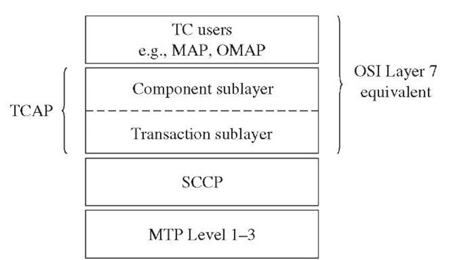
Figure 2-15 shows the TCAP in the CCS7 Layer and its relationship with the OSI reference model.
Structure of TCAP
As shown in Figure 2-15, TCAP is structured into two sublayers;
■ Component sublayer
■ Transaction sublayer
Component sublayer. The component sublayer gets the information components from the TC users/applications. The TC user expects that these components will be delivered to the remote entity in sequence. The information components are basically the primitives and parameters necessary to invoke an operation at the remote entity. The following five types of components are defined:
■ Invoke
■ Return result (not last)
■ Return result (last)
■ Return error
■ Reject
The invoke component is used to request that an operation be performed at the receiver end. The invoke component indicates the operation type, using operation code. The operation codes are specific to a TC user.
The receiving entity, on receiving the invoke component with a specific operation code, performs the operation and returns the outcome of the operation in the return result component. It may be possible that one return result component may not be able to convey the result because of the limited capacity offered by the UDT message.
Figure 2-15 TCAP position in CCS7 protocol stack.
In such cases, the result data is segmented and transferred in the return result (not last) component. The last segment is transferred using the return result (last) component.
The return error component is used to report an unsuccessful operation. This does not necessarily mean a failure or fault. For example, if an entity invokes an operation in an MSC that results in paging a mobile station (MS), and the MS does not respond, then the return error component will indicate an unsuccessful operation.
The reject component reports the receipt and the rejection of an incorrect component. The reject component also reports if the application is unable to process a component because of problems.
Transaction sublayer. The transaction sublayer is responsible for managing the exchange of MSUs containing components between two entities. It provides the necessary information to the signaling point to route the components to the remote entity.
There are five transaction sublayer message types supported:
■ Begin
■ Continue
■ End
■ Unidirectional
■ Abort
The ‘Begin’ message is used to open a dialogue with a remote peer transaction sublayer. The begin message may include one or more components. The dialogue is identified by an originating transaction ID (OTID).
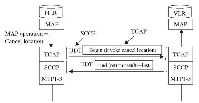
Figure 2-16 TCAP messages.
The ‘Continue’ message is used to transport additional information following a ‘Begin’ message. The first ‘Continue’ message in response to a begin message confirms the acceptance of application context and protocol. It comprises both OTID and terminating transaction ID (TTID). The ‘Continue’ message may have one or more components.
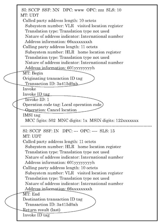
Figure 2-17 TCAP transaction and component sublayers.
The ‘End’ message is used to terminate a transaction. The ‘End’ message may have one or more components.
The unidirectional message is used for unstructured dialogue.
The unidirectional ‘Abort’ message is used to terminate a dialogue any time an error occurs or a requested operation cannot be processed.
Figure 2-16 shows that the MAP entity in an HLR invokes the cancel location operation in the remote entity, i.e., the VLR.
Figure 2-17 shows the protocol decode of the messages that flow between the HLR and the VLR to invoke a MAP cancel location operation in the VLR. Note that the MAP message is carried over as an invoke component in a TCAP dialogue initiated by the ‘Begin’ message and identified by a transaction ID 3a415d0a hex.


