The SCCP supplements the MTP transport capabilities to provide enhanced connectionless and connection-oriented network services. Together with the MTP, it provides the capabilities corresponding to Layers 1 to 3 of the OSI model. The combined MTP and SCCP services are called the Network Service Part (NSP).
The SCCP structure is illustrated in Figure 2-10. As shown, it consists of four functional blocks.
1. SCCP connection-oriented (CO) control function handles the establishment, release, and supervision of the data transfer on logical signaling connections.
2. SCCP connectionless (CL) control provides the connectionless transfer of data units.
3. SCCP management handles the status information of the SCCP network.
4. SCCP routing handles the routing of SCCP messages. This includes routing based on global title and distribution of messages based on the subsystem number.
Figure 2-10 SCCP overview.
Four classes of network transport services are provided by the SCCP;
Class 0: Basic sequenced connectionless Class 1: Sequenced connectionless Class 2: Basic connection-oriented Class 3: Flow control connection-oriented
Connectionless signaling
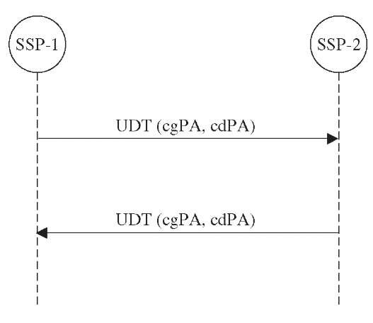
In both Class 0 and Class 1 connectionless services, the messages between SCCP users are transferred without establishing a logical connection. Each message is sent independently of the previously sent message. The SCCP user data is sent in a Unit Data (UDT) message. The difference between Class 0 and Class 1 is that Class 1 tries to offer (not guaranteed) in-sequence delivery by setting up the same SLS code for all the messages in a transaction. Figure 2-11 illustrates the data transfer between two SCCP users using SCCP functions at SSP-1 and SSP-2. The UDT contains the calling party (cgPA) and called party (cdPA) address, which identify the destination and origin of the message. Note that the UDT messages can take any available signaling path to reach the destination.
Figure 2-11 Connectionless services.
Connection-oriented signaling
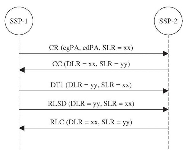
In connection-oriented service, a logical connection is established between the SCCP users before the data transfer takes place. The logical connection establishment and subsequent data transfer procedure is shown in Figure 2-12.
1. On request from an SCCP user for a connection-oriented data service, the originating SSP-1 sends a CR (connection request) message to the SCCP located in SSP-2. In addition, to set up information— i.e., calling and called part address—SSP-1 also adds a source local reference (SLR = xx in the example shown in Figure 2-12).
Figure 2-12 Connection-oriented service.
2. SSP-2, on receiving the message, returns a connection confirmed (CC) message to SSP-1. The CC message contains a destination local reference (DLR), which is set equal to the SLR value received in the CR message. It also adds its own SLR value (yy in this case).
3. With known values of an SLR and a DLR, a logical connection is now established. The user data can be exchanged between SSP-1 and SSP-2 using this logical connection. Each subsequent message from SSP-1 will have SLR = xx and DLR = yy. All the messages from SSP-2 will have SLR = yy and DLR = xx.
The user data is sent in Data Form 1 (DT1) for Class 2 and in DT2 for Class 3 of connection-oriented services. The Class 3 service provides flow control. This is achieved by assigning sequence numbers to each message. The monitoring capabilities in SCCP ensure in-sequence delivery and notification to SCCP users in case of message loss.
SCCP message format
The structure of SCCP message is shown in Figure 2-13. The SCCP messages are transferred between nodes in the Level 3 MSU. The SCCP MSU is identified by the SIO value, which is set to 03hex. As shown in the figure, the SCCP message is of variable length. It consists of a routing label, message type, and a few mandatory and optional information elements.
Figure 2-13 SCCP message format.
TABLE 2-2 SCCP Messages
Table 2-2 lists the SCCP messages and the name of the protocol class that each message belongs to.
SCCP routing control
The purpose of SCCP is to enable end-to-end routing. This is intended to enhance MTP Level 3 point-to-point routing capabilities using point codes. In the case of SCCP, the routing is based on any combination of following elements:
■ Point codes
■ Calling and called party number
■ Subsystem number
The calling and called party address information elements in an SCCP message contain one octet to indicate the address type and a variable number of octets containing the actual address. Two basic address types used are:
1. Global title. A global title (GT) is a regular directory number that does not contain the exact information to enable routing in a signaling network. An SCCP translation function is required to derive routing information on each node.
2. Destination point code and subsystem number. The subsystem number (SSN) identifies an SCCP user function, e.g. VLR or MSC. Table 2-3 lists the defined SSN values and subsystem names. The DPC and the SSN combination allow direct routing by the SCCP and MTP without any translation required.
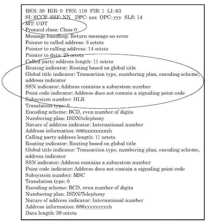
Figure 2-14 shows protocol decodes for an SCCP UDT message. The routing is based on global title and SSN is included.
SCCP management
SCCP provides its own management function. It is mainly intended to handle the status information of the SCCP network. This function also includes dynamic updating of routing table, based on the availability of subsystems (e.g., HLR or MSC). SCCP management messages are sent in the data part of UDT messages. The SCCP management function supports the following message types.
Subsystem status test (SST). This message is used to probe a subsystem that has been reported as not available previously.
Subsystem prohibited (SSP). This message indicates that a subsystem has been taken out of service.
Subsystem allowed (SSA). This message indicates that a previously unavailable subsystem is now available.
TABLE 2-3 SSN Values
|
SSN (hex) |
Subsystem |
|
0 |
SSN not known |
|
1 |
SCCP management |
|
2 |
Reserved |
|
3 |
ISUP |
|
4 |
OMAP |
|
5 |
MAP |
|
6 |
HLR |
|
7 |
VLR |
|
8 |
MSC |
|
9 |
EIR |
|
0A |
AUC |
|
0B |
SMSC |
|
FE |
BSSAP |
Figure 2-14 Partial decode of an SCCP UDT message.


