3.4
The stack pointer may be used with all the index addressing modes, but its uses have special meaning. These uses correspond to pushing and pulling, and they support reentrancy and recursion. Also, the index registers X and Y may be used as auxiliary stack pointers. This section shows these variations of index addressing.
The instruction ldaa 1, sp+ is essentially the same as pula because both pull a byte from the (hardware) stack into accumulator A. Similarly, the instruction ldd 2,sp+ is essentially the same as puld; the instruction staa 1,-sp is essentially the same as psha; and the instruction std 2,-sp is essentially the same as pshd. The differences between these pairs of instructions is in their length and execution time and in the effect they have on condition codes. The instructions pula, psha, puld, and pshd are usually preferred because they are faster and shorter, but the instructions ldaa 1, sp+, std 2 , -sp, and so on may be used if pulling or pushing needs to set the condition codes for a future conditional branch instruction.
Moreover, auto increment addressing can be used with other instructions to pull a byte or 16-bit word and simultaneously use the pulled data in an instruction. The sequence:

is often used in code generated by C and C++ compilers to add accumulator B to accumulator A (equivalent to the simpler instruction aba). However, this push-and-pull-into-an-instruction technique can be used with other instructions like an da and addd. The sequence:

is often used in code generated by C and C++ compilers to add index register X to accumulator D.

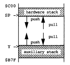
Figure 3.11. A Stack Buffer for Two Stacks
The hardware stack, pointed to by SP, is useful for holding a subroutine’s arguments and local variables. This will be discussed at the end of this section. However, because return addresses are saved on and restored from the hardware stack, we sometimes need a stack that is not the same as that hardware stack. For instance, we may push data in a subroutine, then return to the calling routine to pull the data. If we use the hardware stack, data pushed in the subroutine need to be pulled before the subroutine is exited, or that data will be pulled by the rts instruction, rather than the subroutine’s return address. A second stack can be implemented using an index register such as Y. If index register Y is also needed for other purposes in the program, this second stack pointer can be saved and restored to make it available only when the second stack is being accessed.
Figure 3.11 illustrates that a second auxiliary stack may use the same buffer as the hardware stack. The hardware stack pointer is initially loaded with the address of (one past) the high address of the buffer, while the second auxiliary stack pointer (Y) is loaded with (one below) the low end of the same stack buffer. The second stack pointer is initialized as: ldy #$b7f . Accumulator A can be pushed using staa 1,+y. A byte can be pulled into accumulator A using ldaa 1, y- . A 16-bit word can be pushed and pulled in an obvious way. Observe that auto incrementing and auto decrementing are reversed compared to pushing and pulling on the hardware stack, because, as seen in Figure 3.11, their directions are reversed.
The advantage of having the second stack in the same buffer area as the hardware stack is that when one stack utilizes little of the buffer area, the other stack can use more of the buffer, and vice versa. You only have to allocate enough buffer storage for the worst-case sum of the stack sizes, whereas if each stack had a separate buffer, each buffer would have to be larger than the worst case size of its own stack.
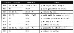
A recursive subroutine is one that calls itself. The procedure to calculate n factorial, denoted n!, is recursive; for any positive nonzero integer n, if n is one, n! is 1, otherwise n! is (n-1)! * n. The subroutine in Figure 3.12 calculates n!; upon entry, n is in accumulator D, and upon exit, n! is in accumulator D.

Figure 3.12. Subroutine to Compute n! Recursively
Although recursive subroutines implement a scientist’s induction mechanism, they are not always useful. Consider the alternative in Figure 3.13 that uses a loop. The alternative is significantly more efficient. The recursive solution uses the hardware stack as a counter, pushing a 2-byte return address and 2-byte saved parameter value each time it calls itself to reduce its parameter by 1. If n is 5, this subroutine uses up 20 bytes of stack storage. This is not efficient. But there are efficient recursive subroutines, especially for following linked list data structures, as we will see in topic 9.
A subroutine is reentrant if il can be stopped, for instance because of an interrupt, and then resumed, and it will get the same result as if it were not stopped, even though the interrupt handler might call this subroutine during its execution. Also, a time-sharing computer uses interrupts to switch between tasks or threads that share a computer. Reentrant subroutines can be used by each task or thread, without concern that, when a thread or task is stopped during execution of the subroutine, another thread will execute the subroutine. The subroutine in Figure 3.14 is nonreentrant, and following it is a reentrant subroutine: both clear five bytes beginning at location $824.

Figure 3.13. Subroutine to Compute n! in a Loop

Figure 3.14. Non reentrant Subroutine to Clear Memory
This program fails to work correctly if it is interrupted after the STAA instruction is executed, and before the RTS instruction is executed and the interrupt handler calls this subroutine. The second call to this subroutine will wipe out the counter at location $822 because the second call will also use this same location and will leave it cleared when the first call to this subroutine resumes execution. The first call to this subroutine will not work the same way if the interrupt occurs as it does if the interrupt doesn’t occur. However, the subroutine in Figure 3.15 will work correctly if it is similarly interrupted.
The key idea behind both recursion and reentrancy is to keep data on the stack. The stack provides new storage locations for each instantiation of the subroutine to keep its variables separate from the variables of other instantiations, so they aren’t destroyed.
Note that the decrement instruction accesses the counter on the stack without pulling the byte. If three 1-byte items were pushed on the stack, the instruction LDAA 2, SP will read into accumulator A the first byte pushed without removing it from the stack. In general, items can be pushed on the stack at the beginning of a procedure and pulled off at the end of the procedure. Within the procedure the items can be read and written using offsets from the stack pointer.

Figure 3.15. Reentrant Subroutine to Clear Memory


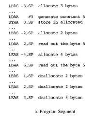
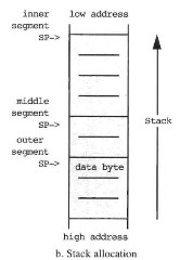
Figure 3.16. A Stack Buffer for Nested Segments
The concept of storing data on the stack leads to nested allocation, access, and deallocation of local variables. Nested segments are commonly used in C and C++ programs to call procedures; the outer segment holds parameters passed to the procedure, and the inner segment stores some of the local variables of a procedure. Further, C and C++ programs nest segments within a procedure to hold temporary variables needed to evaluate a C statement. This concept is fully explained in terms of a program trace, which is introduced First. Then we consider a simple trace, and then a nested trace.
One can record a program’s instructions in the exact order they are executed to obtain a trace. Simple program segments without branching statements are the same as their traces. If a program has a loop that is executed five times, the trace has five copies of the instruction sequence in the loop.
In a program trace, one can allocate local variables by pushing items on the stack, and one can deallocate them by pulling them from the stack, as already illustrated in this section. Once allocated, the data on the stack can be accessed by reading or writing the contents as discussed above. Moreover, one can allocate several bytes in one instruction, using the LEAS instruction. For instance, to allocate five bytes, execute LEAS -5, SP. By moving the stack pointer SP five locations toward lower memory, five bytes of data can be stored in these bytes that were skipped over. The LEAS instruction can deallocate several words at a time. To deallocate five bytes, execute the instruction LEAS 5, SP. A stack is said to be balanced in a simple trace, which has no alternative branches in it; so it is linear, if the number of allocated bytes equals the number of deallocated bytes, and at no step in the trace, between allocation and deallocation, are more bytes deallocated than were allocated. If, due to conditional branches, there are several possible simple traces to take from when space has been allocated to a given
point in the program, the stack is balanced at that point if it is balanced in every possible simple trace to that point. To balance the stack means to deallocate all the bytes that have been allocated, so that it becomes balanced. We usually allocate space for variables at the beginning of a subroutine and deallocate the space just before we exit the subroutine to balance the stack, but we can have program segments that are not subroutines in which space is allocated at the beginning of the program segment and deallocated at the end of that program segment.
It is possible for a program to have a segment that has space allocated at its beginning and deallocated at its end and to have within it another segment that has space allocated at its beginning and deallocated at its end. This is called a nested allocated segment. Figure 3.16a illustrates a program that has a nested segment where the outer segment allocates three bytes, an inner segment allocates two bytes, and an inner segment of it allocates another four bytes. The outer segment writes the number 5 in its lowest addressed byte, the next inner segment reads this byte into accumulator A, and the innermost segment reads this byte into accumulator B. Note that different offsets are used with the stack pointer to access the same byte of data, due to intervening allocations, but the outer data is available to each inner program segment, even though they are nested.
Stack Index Addressing, Reentrancy, and Recursion (Microcontrollers)
Next post: Examples (Microcontrollers)
Previous post: Relative Addressing and Position Independence (Microcontrollers)
