1.3
Now that we have examined the instruction from static and dynamic points of view, we will look at some simple programs. The machine code for these programs will be described explicitly so that you can try out these programs on a real 6812 and see how they work, or at least so that you can clearly visualize this experience. The art of determining which instructions have to be put where is introduced together with a discussion of the bits in the condition code register. We will discuss what we consider to be a good program versus a bad program, and we will discuss what is going to be in topics 2 and 3. We will also introduce an alternative to the immediate addressing mode using the load instruction. Then we bring in the store, add, software interrupt, and add with carry instructions to make the programs more interesting as we explain the notions of programming in general.
We first consider some variations of the load instruction to illustrate different addressing modes and representations of instructions. We may want to put another number into register A. Had we wanted to put $3E into A rather than $2F, only the second byte of the instruction would be changed, with $3E replacing $2F. The same instruction as
![tmpC-6[2] tmpC-6[2]](http://lh5.ggpht.com/_X6JnoL0U4BY/S09X-7mejMI/AAAAAAAAGI0/POQaFypWhm4/tmpC62_thumb.png?imgmax=800)
could also be written using a decimal number as the immediate operand: for example,
![tmpC-7[2] tmpC-7[2]](http://lh4.ggpht.com/_X6JnoL0U4BY/S09YAqDyB5I/AAAAAAAAGI8/oq05_NaWDro/tmpC72_thumb.png?imgmax=800)
Either line of source code would be converted to machine code as follows:
![tmpC-8[2] tmpC-8[2]](http://lh5.ggpht.com/_X6JnoL0U4BY/S09YCHERqtI/AAAAAAAAGJE/WMs8ccFvA8I/tmpC82_thumb.png?imgmax=800)
We can load register B using a different opcode byte. Had we wanted to put $2F into accumulator B, the first byte would be changed from $86 to $C6 and the instruction mnemonic would be written
![]()
We now introduce the direct addressing mode. Although the immediate mode is useful for initializing registers when a program is started, the immediate mode would not be able to do much work by itself. We would like to load words that are at a known location but whose actual value is not known at the time the program is written. One could load accumulator B with the contents of memory location $0840. This is called direct addressing, as opposed to immediate addressing. The addressing mode, direct, uses no pound sign “#” and a 2-byte address value as the effective address; it loads the word at this address into the accumulator. The instruction mnemonic for this is
![]()
and the instruction appears in memory as the three consecutive bytes.
![tmpC-11[2] tmpC-11[2]](http://lh3.ggpht.com/_X6JnoL0U4BY/S09YGie5pVI/AAAAAAAAGJc/ZNbOk6f-42A/tmpC112_thumb.jpg?imgmax=800)
Notice that the “#” is missing in this mnemonic because we are using direct addressing instead of immediate addressing. Also, the second two bytes of the instruction give the address of the operand, high byte of the address first.
The store instruction is like the load instruction described earlier except that it works in the reverse manner (and a STAA or STAB with the immediate addressing mode is neither sensible nor available). It moves a word from a register in the MPU to a memory location specified by the effective address. The mnemonic, for store from A, is STAA; the instruction
![]()
will store the byte in A into location 2090 (decimal). Its machine code is
![tmpC-13[2] tmpC-13[2]](http://lh4.ggpht.com/_X6JnoL0U4BY/S09YYHVEXnI/AAAAAAAAGJs/9N0z72AABGI/tmpC132_thumb.jpg?imgmax=800)
where we note that the number 2090 is stored in hexadecimal as S082A. With direct addressing, two bytes are always used to specify the address even though the first byte may be zero.
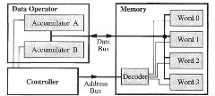
Figure 1.3. Registers and Memory
Figure 1.3 illustrates the implementation of the load and store instruction in a simplified computer, which has two accumulators and four words of memory. The data operator has accumulators A and B, and a memory has four words and a decoder. For the instruction LDAA 2, which loads accumulator A with the contents of memory word 2, the controller sends the address 2 on the address bus to the memory decoder; this decoder enables word 2 to be read onto the data bus, and the controller asserts a control signal to accumulator A to store the data on the data bus. The data in word 2 is not lost or destroyed. For the instruction STAB 1, which stores accumulator B into the memory word 1, the controller asserts a control signal to accumulator B to output its data on the data bus, and the controller sends the address 1 on the address bus to the memory decoder; this decoder enables word 1 to store the data on the data bus. The data in accumulator B is not lost or destroyed.
The ADD instruction is used to add a number from memory to the number in an accumulator, putting the result into the same accumulator. To add the contents of memory location $0BAC to accumulator A, the instruction
![]()
appears in memory as
![tmpC-16[2] tmpC-16[2]](http://lh3.ggpht.com/_X6JnoL0U4BY/S09YfJSjdTI/AAAAAAAAGKE/BEL5Ao_Ta5Y/tmpC162_thumb.png?imgmax=800)
The addition of a number on the bus to an accumulator such as accumulator A is illustrated by a simplified computer having a data bus and an accumulator (Figure 1.4).
The data operator performs arithmetic operations using an adder (see Figure 1.4). Each 1-bit adder, shown as a square in Figure 1.4b, implements the truth table shown in Figure 1.4a. Registers A, B, and S may be any of the registers shown in Figure 1.2 or instead may be data from a bus. The two words to be added are put in registers A and B, Cin is 0, and the adder computes the sum, which is stored in register S. Figure 1.4c shows the symbol for an adder. Figure 1.4d illustrates addition of a memory word to accumulator A. The word from accumulator A is input to the adder while the word on the data bus is fed into the other input. The adder’s output is written into accumulator A.
When executing a program, we need an instruction to end it. When using the debugger MCUez or HiWave with state-of-the-art hardware, background (mnemonic BGND) halts the microcontroller, when using the debugger DBUG_12 with less-expensive hardware, software interrupt (mnemonic SWI) serves as a halt instruction. In either case, the BRA instruction discussed in the next topic can be used to stop. When you see the instruction SWI or BGND in a program, think “halt the program.”
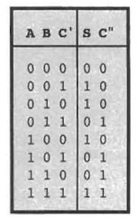
a. Truth Table
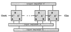
b. Parallel Adder
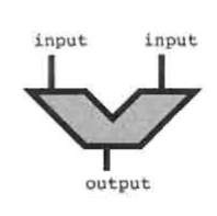
c. Symbol for an Adder

d. Adder in a Data Operator
Figure 1.4. Data Operator Arithmetic
The four instructions in Figure 1.5 can be stored in locations 2061 through 2070, or S80D through $816 in hexadecimal; its execution adds two numbers in locations $840 and $841, putting the result into location $842.
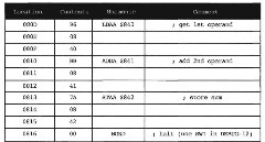
Figure IS. Program for 8-Bit Addition

Figure 1.6. Bits in the Condition Code Register
We will now look at condition code bits in general and the carry bit in particular. The carry bit is really pretty obvious. When you add by hand, you may write the carry bits above the bits that you are adding so that you will remember to add it to the next bit. When the microcomputer has to add more than eight bits, it has to save the carry output from one byte to the next, which is Cout in Figure 1.4b, just as you remembered the carry bits in adding by hand. This carry bit is stored in bit C of the condition code register shown in Figure 1.6. The microcomputer can input this bit into the next addition as Cin in Figure 1.4b. For example, when adding the 2-byte numbers $349E and $2570, we can add $9E and $70 to get $0E, the low byte of the result, and then add $34. $25, and the carry bit to get $5A, the high byte of the result. See Figure 1.7. In this figure, C is the carry bit obtained from adding the contents of locations 11 and 13; (m) is used to denote the contents of memory location m, where m may be 10, 11, 12, etc. The carry bit (or carry for short) in the condition code register (Figure 1.6) is used in exactly this way.
The carry bit is also an error indicator after the addition of the most significant bytes is completed. As such, it may be tested by conditional branch instructions, to be introduced later. Other characteristics of the result are similarly saved in the controller’s condition code register. These are, in addition to the carry bit C, N (negative or sign bit), Z (zero bit), V (two’s-complement overflow bit or signed overflow bit), and H (half-carry bit) (see Figure 1.6). How 6812 instructions affect each of these bits is shown in the CPU 12 Reference Guide, Instruction Set Summary, in the rightmost columns.
We now look at a simple example that uses the carry bit C. Figures 1.8 and 1.9 list two equally good programs to show that there is no way of having exactly one correct answer to a programming problem. After the example, we consider some ways to know if one program is better than another. Suppose that we want to add the two 16-bit numbers in locations $810, $811 and $812, $813, putting the sum in locations $814, $815. For all numbers, the higher-order byte will be in the smaller-numbered location. One possibility for doing this is the following instruction sequence, where, for compactness, we give only the memory location of the first byte of the instruction.
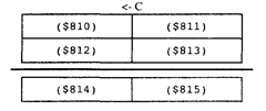
Figure 1.7. Addition of Two-Byte Numbers

Figure 1.8. Program for 16-Bit Addition
In the program segment above, the instruction ADCA $812 adds the contents of A with the contents of location $812 and the C condition code bit, putting the result in A. At that point in the sequence, this instruction adds the two higher-order bytes of the two numbers together with the carry generated from adding the two lower-order bytes previously. This is, of course, exactly what we would do by hand, as seen in Figure 1.7. Note that we can put this sequence in any 19 consecutive bytes of memory as long as the 19 bytes do not overlap with data locations $810 through $815. Finally, the notation A:B is used for putting the accumulator A in tandem with B or concatenating A with B. This concatenation is just the double accumulator D. We could also have used just one accumulator with the following instruction sequence.
In this new sequence, the load and store instructions do not affect the carry bit C. (See the CPU12RG/D manual Instruction Set Summary. We will understand why instructions do not affect C as we look at more examples.) Thus, when the instruction ADCA $812 is performed, C has been determined by the ADDB $813 instruction.
The two programs above were equally acceptable. However, we want to discuss guidelines to writing good programs early in the topic, so that you can be aware of them to know what we are expecting for answers to problems and so that you can develop a good programming style. A good program is shorter and faster and is generally clearer than a bad program that solves the same problem. Unfortunately, the fastest program is

Figure 1.9. Alternative Program for 16-Bit Addition
almost never the shortest or the clearest. The measure of a program has to be made on one of the qualities, or on one of the qualities based on reasonable limits on the other qualities, according to the application. Also, the quality of clarity is difficult to measure but is often the most important quality of a good program. Nevertheless, we discuss the shortness, speed, and clarity of programs to help you develop good programming style.
The number of bytes in a program (its length) and its execution time are something we can measure. A short program is desired in applications where program size affects the cost of the end product. Consider two manufacturers of computer games. These products feature high sales volume and low cost, of which the microcomputer and its memory are a significant part. If one company uses the shorter program, its product may need fewer ROMs to store the program, may be substantially cheaper, and so may sell in larger volume. A good program in this environment is a short program. Among all programs doing a specific computation will be one that is the shortest. The quality of one of these programs is the ratio of the number of bytes of the shortest program to the number of bytes in the particular program. Although we never compute this static efficiency of a program, we will say that one program is more statically efficient than another to emphasize that it takes fewer bytes than the other program.
The CPU12RG/D manual Instruction Set Summary gives the length of each instruction by showing its format. For instance, the LDAA #$2F instruction is shown alphabetically under LDAA in the line IMM. The pattern 86 ii, means that the opcode is $86 and there is a one-byte immediate operand ii, so the instruction is two bytes long.
The speed or execution time of a program is prized in applications where the microcomputer has to keep up with a fast environment, such as in some communication switching systems, or where the income is related to how much computing can be done. A faster computer can do more computing and thus make more money. However, speed is often overemphasized: “My computer is faster than your computer.” To show you that this may be irrelevant, we like to tell this little story about a computer manufacturer. This is a true story, but we will not use the manufacturer’s real name for obvious reasons. How do you make a faster version of a computer that executes the same instruction? The proper answer is that you run a lot of programs, and find instructions that are used most often. Then you find ways to speed up the execution of those often-used instructions. Our company did just that. It found one instruction that was used very, very often: It found a way to really speed up that instruction. The machine should have been quite a bit faster, but it wasn’t! The most common instruction was used in a routine that waited for input-output devices to finish their work. The new machine just waited faster than the old machine that it was to replace. The moral of the story is that many computers spend a lot of time waiting for input-output work to be done. A faster computer will just wait more. Sometimes speed is not as much a measure of quality as it is cracked up to be. But then in other environments, it is the most realistic measure of a program. As we shall see in later topics, the speed of a particular program can depend on the input data to the program. Among all the programs doing the same computation with specific input data, there will be a program that takes the fewest number of clock cycles. The ratio of this number of clock cycles to the number of clock cycles in any other program doing the same computation with the same input data is called the dynamic efficiency of that program. Notice that dynamic efficiency does depend on the input data but not on the clock rate of the microprocessor. Although we never calculate

Figure 1.10. Most Efficient Program for 16-Bit Addition
dynamic efficiency explicitly, we do say that one program is more dynamically efficient than another to indicate that the first program performs the same computation more quickly than the other one over some range of input data.
The CPU12RG/D manual Instruction Set Summary gives the instruction timing. For instance, the LDAA #$2F instruction is shown alphabetically under LDAA for the mode IMM. The Access Detail column indicates that this instruction takes one memory cycle of type P, which is a program word fetch. Generally, a memory cycle is 125 ns.
The clarity of a program is hard to evaluate but has the greatest significance in large programs that have to be written by many programmers and that have to be corrected and maintained for a long period. Clarity is improved if you use good documentation techniques, such as comments on each instruction that explain what you want them to do, and flowcharts and precise definitions of the inputs, outputs, and the state of each program, as explained in texts on software engineering. Some of these issues are discussed in topic 5. Clarity is also improved if you know the instruction set thoroughly and use the correct instruction, as developed in the next two topics.
While there are often two or more equally good programs, the instruction set may provide significantly better ways to execute the same operation, as illustrated by Figure 1.10. The 6812 has an instruction LDD to load accumulator D, an instruction ADDD to add to accumulator D, and an instruction STD to store accumulator D, which, for accumulator D, are analogous to the instructions LDAA, ADDA, and STAA for accumulator A. The following program performs the same operations as the programs given above but is much more dynamically and statically efficient and is clearer.
If you wish to write programs in assembly language, full knowledge of the computer’s instruction set is needed to write the most efficient, or the clearest, program. The normal way to introduce an instruction set is to discuss operations first and then addressing modes. We will devote topic 2 to the discussion of instructions and topic 3 to the survey of addressing modes.
In summary, you should aim to write good programs. As we saw with the example above, there are equally good programs, and generally there are no best programs. Short, fast, clear programs are better than the opposite kind. Yet the shortest program is rarely the fastest or the clearest. The decision as to which quality to optimize is dependent on the application. Whichever quality you choose, you should have as a goal the writing of clear, efficient programs. You should fight the tendency to write sloppy programs that just barely work or that work for one combination of inputs but fail for others. Therefore, we will arbitrarily pick one of these qualities to optimize in the problems at
the end of the topics. We want you to optimize static efficiency in your solutions, unless we state otherwise in the problem. Learning to work toward a goal should help you write better programs for any application when you train yourself to try to understand what goal you are working toward.
A Few Instructions and Some Simple Programs (Microcontrollers)
Next post: Variable Word Width (Microcontrollers)
Previous post: The Instruction (Microcontrollers)
