3.2
This section introduces a collection of addressing modes that are encoded in a post byte and that use index registers in the address calculation. To improve efficiency, the controller is often provided with a few registers that could be used to obtain the effective
address. These registers are called pointer or index registers. Obtaining an address from such an index register would be faster because the number of bits needed to specify one of a few registers is much less than the number of bits needed to specify any word in memory that holds the address. Moreover, index addressing is the most efficient mode to handle many data structures, such as character strings, vectors, and many others, as we discuss later. With this potential, index registers have been used in a number of similar modes, called collectively index addressing modes, which are introduced below.
Before we get into the modes of index addressing we have to discuss the idea of a post byte. As noted earlier, the 6832 is a successor of the 6811. The latter had only the modes inherent, immediate, page zero, direct, and one form of index addressing discussed below. To keep the same customers that they had for the 6811 happy with the newer machine. Motorola opted to make the 6812 as similar as possible to its predecessors. But to introduce more addressing modes, they needed more room in the instruction. The 6812 is as similar to its predecessors as possible, using the same opcodes in many cases. The extra addressing modes were provided by including an extra byte, right after the opcode byte, for addressing information only and then only for variations of index addressing [hat are used on the 6812. This byte is the post byte.
The 6812 uses index addressing with two index registers, X and Y, the stack pointer SP and program counter PC. Although these have equivalent addressing capabilities, the SP register and program counter have special uses that are discussed in later sections of this topic. Generally, all the addressing modes described for X below also apply to the other registers. First, there are load instructions that can load these registers. For example, the instruction
ldx #$843
will load the 16-bit X register with $843. It is machine coded very much like the ldaa immediate instruction. (See the CPU12RG/D manual.) In the following examples, assume X is $843.
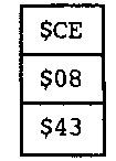
The other registers can be loaded using similar instructions, and other addressing modes can be used to get the two bytes to be put in the index register. In all cases, the effective address determined by the instruction is used to get the first byte to be put into the high byte of the index register. The effective address plus one is used to get the second byte to be put into the low byte of the index register.
Coding of the post byte is shown in Figure 3.2. You can read the tree shown therein from left to right to decode a post byte, or from right to left to encode an index mode into a post byte. To decode a post byte, start at the tree root, and proceed right if bit 5 is zero, otherwise go down. Then check the bit(s) indicated at the next branching point, to determine where to go next, and so on. To encode an index mode into a post byte, locate the index mode on the right, then follow the tree from there to the root, noting the settings of the bits along the way that constitute the post byte code. This information is also shown in the CPU 12RG/D manual, in Table 1 and Table 2, using other formats.
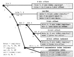
Figure 3.2. Post Byte Coding
Index addressing uses a signed offset in the post byte or the post byte and one or two bytes following it. When executed, the offset is added to the index register, say X. to get the effective address of the operand or result in memory. See Figure 3.4.
Effective addresses are frequently within ±16 locations of the index register address, and many others are within ±256 locations. Thus, for greater efficiency, a shortest 5-bit or a 9-bit option is used for some cases, but a full 16-bit index option is also available for cases that do not fall in the range of ±256 locations. The 5-bit offset is entirely contained in the post byte. The 9-bit offset's sign bit is in the post byte, and the remaining eight bits are in the following byte. The 16-bit offset is in the two bytes following the post byte.
The shortest mode with a 5-bit offset will always be used when the offset is between -16 and +15. The instruction LDAA 1, X loads the number contained in location I + $843 into accumulator A. The post byte for this 5-bit offset mode (see Figure 3.2) has a zero in bit 5, the index register in bits 7 and 6 (00 is X, 01 is Y, 10 is SP, and 11 is PC), and the offset in bits 4 to 0. LDAA l,X's machine code is:
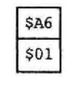

Figure 33. Program Segment to Add Two Bytes Using Vector Indexing
$A6 is the opcode byte for any LDAA index mode, and $01 is the post byte. The saved offset is sign extended and added to the index register (see Figure 3.4).
The program segment in Figure 3.3 adds the word at $844 to the word at $845. putting the sum in $846. No instruction's execution changes the contents of X.
The 9-bit option will be used when the offset is between -256 and +255 or when the offset is between -16 and +15 and a "<" symbol, as it is used in the page zero mode, is written preceding the offset. The instruction
![]()
loads the number contained in location $11+ $843 = $854 into accumulator A. The post byte for this 9-bit offset mode (see Figure 3.2) has ones in bits 7 to 5, the index register in bits 4 and 3 (00 is X, 01 is Y, 10 is SP, and 11 is PC), a zero in bits 1 and 2, and the sign bit of the offset in bit 0. Like the 5-bit offset case, the saved offset is sign extended and added to the index register to get the effective address, as illustrated by Figure 3,4. The machine code is
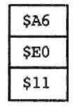
where $A6 is the opcode byte for any index option with LDAA, $E0 is the post byte, and bit 0 of the post byte and the next byte $11 are the offset.
When a larger offset is needed, the full 16-bit offset option can be used. The 16-bit option will be used when the offset is outside the range -256 and +255 or when the offset is in this range and a ">** symbol, as it is used in the direct mode, precedes the offset. The instruction
![]()

Figure 3.4. Offset Calculation
loads the number contained in location $3012 + $843 = $3855 into accumulator A. The post byte for this 36-bit offset mode (see Figure 3.2) has ones in bits 7 to 5, the index register in bits 4 and 3 (00 is X, 01 is Y, 10 is SP, and 11 is PC), and 010 in bits 2 to 0. The machine code is given by
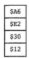
where $A6 is the opcode byte for any index option with LDAA, $E2 is the the post byte, and $3012 is the 16-bit two's-complement offset. The saved offset is added to the index register to get the effective address, as illustrated by Figure 3.4.
In short, addresses requiring several accesses are kept in index registers, if possible, and utilize the more efficient index addressing. Shorter offsets produce more efficient programs and can be used if the index register value is close to the effective addresses that will be used. But while negative offsets are mechanically as usable as positive offsets to more often use shorter offsets, positive offsets are often preferred for clarity.
The 5-, 9-, and 16-bit offset index addressing modes are useful for reading data out of a vector. Suppose a 10-element vector of 8-bit items has element 0 at $843, element 1 at $844, element 2 at $845, and so on. Then if X has $843, then
![]()
puts element 2 into accumulator A. Suppose now that a 10-element vector of 8-bit items has element 0 at $872, element 1 at $873, element 2 at $874, and so on. Then if X has $872, this instruction still gets element 2 out of the vector. This instruction uses the efficient 5-bit offset mode. The following instruction gets element i from the vector beginning at $843 into accumulator A, where the vector index i is in index register X:
![]()
This instruction uses the less efficient 16-bit offset mode, but it lets the variable index be in the X index register.
Index registers can be either autoincremented or autodecremented before or after being used in effective address calculations. It is denoted by a delta value between 1 and

Figure 33. Auto increment Address Calculation
8, a comma, and the register name with a "+" or "-" symbol. If "+" appears, the index register is incremented by the delta value, and if "-" appears, the index register is decremented by the delta value: if this symbol appears before the register name, incrementing or decrementing is done before effective address calculation, and if the symbol appears after the register, incrementing or decrementing is done after the calculation. Consider an example of postincrementing by I; if X had $843,
![]()
loads the contents from location $843 into A and then increments the contents of X by 1 to make it $844. For an example of preincrementing by I, if X had the value $843,
![]()
increments the contents of X by 1, and then loads the contents from location $844 into A. An example of postincrementing by 2, if X had the value $843,
![]()
loads the contents from locations $843 and $844 into D and then increments the contents of X by 2 to make it $845. For an example of predecrementing, if X had the value $843.
![]()
decrements the contents of X by 1 to make it $842 and then loads the contents from location $842 into A. Delta can be as high as 8.
These addressing modes are encoded in the post byte as follows (see Figure 3.2): Bits 7 and 6 identify the register (00 is X, 01 is Y, and 10 is SP, but 11 is not used for this mode), bit 5 is 1, bit 4 is 0 if the index value changes before address calculation and 1 if after, bit 3 is 1 if decrementing and 0 if incrementing. For incrementing, bits 2 to 0 are the value of delta minus 1 (or equivalently, delta is the low-order three bits plus 1). For decrementing, bits 2 to 0 are the value of delta, as a negative two's-complement number, to be added to the index register. For example, for LDAA 1, X+ the post byte is $30. for LDAA 1,+X the post byte is $20, for LDD 2 , X+ the post byte is $31, for LDAA 1, -X it is $2F, and for LDAA 2, -X it is $2E, and so on.
Figure 3.5 illustrates how the delta value fetched from memory can be added to the index register. The index value before or after modification can be used as the effective address by appropriately setting the switch that determines the effective address,
Consider addition again. If you want to add the word at location $843 with the word at location $844, putting the result at location $845, execute the code in Figure 3.6.

Figure 3.6. Program Segment to Add Two Bytes Using Auto incrementing

Figure 3.7, Accumulator Index Address Calculation
Note that these increment and decrement modes produce a side effect. They not only compute the effective address, they also change the value in the index register used to get the address. No other addressing mode has such a side effect. We will see how useful these options are when we look at some examples later in this topic.
Sometimes, the effective address is the sum of two variable numbers. The index register can be used to hold one of the variables, and an accumulator, A, B, or D, can hold the other number, as in LDAB A,X. The sign-extended accumulator (A) is added to the index register (X) to provide the effective address. The effective address can be obtained as in Figure 3.7. This is called accumulator indexed addressing.
The contents of the registers A and B are treated as 8-bit two's-complement numbers in these instructions while the contents of D may be treated as a 16-bit two's-complement number or an unsigned 16-bit number, because the sum of the contents of D and the contents of any 16-bit index register, truncated to 16 bits, is the same unsigned 16-bit number in either case. The post byte for accumulator index addressing is as follows: Bits 7 to 5 and bit 2 are 1, the index register is encoded in bits 4 and 3 (00 is X. 01 is Y. 10 is SP, and 11 is PC), and the accumulator is encoded in bits I and 0 (00. A: 01, B; and 1 f, D). The instruction LDAB A, X is encoded as follows:
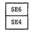
Accumulator index addressing modes are useful for reading data out of a vector where the location of the vector in memory, as well as the vector index, are determined at run time. Suppose a 10-element vector of 8-bit items has element 0 at $843, element 1 at $844, element 2 at $845, and so on. Then if X has $843, and accumulator A is 2. then
![]()
puts element 2 into accumulator A. Suppose now that a 10-element vector of 8-bit items has element 0 at $872, element 1 at $873, element 2 at $874, and so on. Then if X has $872, and accumulator A is 2, then this instruction still gets vector element 2.
Finally, indirect addressing can be combined with accumulator D and 16-bit offset forms of index addressing discussed above. Indirect addressing goes to memory to get the address of the operand, as we describe with examples below. In the 6812, indirect addressing may only be used with these two forms of index addressing. The instruction
![]()
will use the sum of accumulator D and the index register X as an effective address to read two bytes and then use these two bytes as another effective address, to load accumulator A with the word at the latter address. For instance, if D is clear, X contains the value $843, location $843 contains $08, and location $844 contains $67, ldaa [d,x] will load the word at $867 into accumulator A. The post byte for indirect D accumulator index addressing has ones in bits 7 to 5 and 2 to 0, and the index register is specified in bits 4 and 3 (00 is X, 01 is Y, 10 is SP, and 11 is PC). The post byte for the instruction ldaa [ d, x ] is $E7. The instruction
![]()
will use the sum of the 16-bit offset $0012 and the index register X as an address to read two bytes, use these two bytes as another address, and load accumulator A with the word at the latter address. Note that even though the offset of this instruction is an 8-bit number, only 16-bit index addressing is permitted when indirect addressing uses an offset. For instance, if X contains the value $843, location $855 contains $08, and location $856 contains $23, ldaa [ $ 12 , x ] will load the word at $823 into accumulator A. The post byte for indirect 16-bit offset index addressing has ones in bits 7 to 5 and 1 and 0, a zero in bit 2, and the index register is specified in bits 4 and 3 (00 is X, 01 is Y. 10 is SP, and 11 is PC). The post byte for the instruction ldaa [ $ 12 , x ] is $E3.
The leax, leay, and leas instructions can use only index addressing modes, but not index indirect modes. They can be used like a transfer instruction; leax 0, Y will transfer Y to X. More generally, they can be used to add a signed number constant or variable to an index register and possibly put the result in a different register. The instruction leax -3,x subtracts 3 from index register X, while leay a,x adds accumulator A to the value of X and puts the result in Y. These instructions are alternatives to arithmetic instructions such as addd or subd and are especially useful when the result will eventually be put in an index register.
The idea of using a register to form the effective address is very powerful. Several addressing modes were introduced that use this idea. The index mode doesn’t modify the contents of the register, but can add a 5-, 9-, or 16-bit offset to get the effective address. The most common change to an address is to increment or decrement it. The instruction can automatically increment the value in the index register before or after it is used, by one to eight. This will be quite common in some data structures that we meet later. A mode that adds the values of an accumulator to the value of an index register permits one to compute addresses that are derived from two variable values, rather than from a variable and a fixed value. Finally, these modes may be combined with indirect addressing for some special applications. With these modes of addressing, the 6812 is a very powerful microprocessor. With this power, we can show you how to use data structures intelligently to make your programs shorter, faster, and clearer.
