4.2
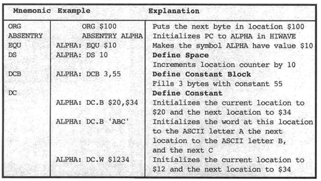
Before looking more closely at how the assembler works, we describe the simplest assembler directives. These are instructions to the assembler that do not result in any actual executable machine coded instructions but are, nevertheless, essential to providing information to the assembler. A number of these will be introduced in this section and are listed in Table 4.3 for your convenience.
If we go back to the example at the beginning of the topic, we recall that what we wanted was to just write down the mnemonics column and let the assembler generate the memory locations and their contents. There must be some additional information given to the assembler; in particular, you have to tell the assembler where to start putting the program or store the variables. This is the purpose of the ORG (for ORiGin) directive. The mnemonic ORG appears in the operation column, and a number (or expression) appears in the operand column. The number in the operand column tells the assembler where to start putting the instruction bytes, or reserved bytes for variables, that follow. For example, if the assembler puts the three bytes for LDX #123 in locations 100,101, and 102, the bytes for the instructions that follow are put consecutively in locations 103. 104, . . .. The operand can be described in decimal, hexadecimal, or binary, following Motorola’s usual conventions. Thus we could replace the ORG directive above by
ORG 256
If there is no ORG directive at the beginning of your program, the assembler will start at memory location 0. There can be more than one ORG directive in a program. AB SENTRY sets the entry point, the initial value of the PC, in the HI WAVE debugger, when a program is loaded, so you don’t have to enter the PC each time you load it.
Table 4.3. Assembler Directives

In all of our examples, we have set aside memory locations for variables. In the last example, we set aside bytes for N, RESULT, and Z. The way we tell the assembler to do this is with the DS (define space) directive. An optional postfix . B indicates bytes are allocated. Here DS appears in the operation field and the number n in the operand field tells the assembler that n bytes are being allocated. If no postfix is used, . B is assumed by default. Alternatively, a postfix of . W indicates that words are allocated so the number of bytes is 2n, and a postfix of .L indicates that long words are allocated so the number of bytes is 4». The label in the DS directive is the variable name that the allocated space is given. The label is given the value of the address of its first, and perhaps only, byte. In the program of Figure 4.3, RESULT is given the value $868, and Z is given the value $86A.
The symbolic address N, which was introduced in §4.1, appears to have a split personality, especially for data. The symbol N is being used in two different ways here, as an address and as the value of a variable. The way to understand this is by analogy to a glass of water. When you say “drink this glass,” the glass is the container, but you mean to drink the contents of the container. You do not expect the listener to be confused because he or she would never think of drinking the container. So too, the symbolic address N stands for the container, variable N’s location, whereas the contents of the container, the word at the address, is variable N’s value. If you think hard enough, it is generally clear which is meant. In the instructions LDX #L or LEAX L,PCR, the symbolic address L is the address of the variable, which is the container. In the instruction LDAA L, the symbolic address represents the contents, in that it is the contents of location L that goes into A. But if you are confused about what is meant, look to see if the symbolic address is being used to represent the container or its contents.
The DS assembler directive assigns a number to the symbolic address or container. In the preceding example, N’s container has the value $868 because $868 is the address of
N. However, the contents of N are not assigned a value, in contrast to a directive DC discussed later. The contents of N are undefined; they are the data that happen to be at location $868 at the time the program is started. The DS directive does not do anything to the value of a variable. We say the memory is allocated but is not initialized.
We have covered everything in the program of Figure 4.2 except the label LOOP, which appears in the label field for a machine instruction, not assembler directives. When a label is used with a machine instruction, it is given the value of the address of the first byte of that instruction. Notice that the value of LOOP in Figure 4.3 is $8a4. This value is also the address of the opcode byte of the EMAXD instruction. Thus the container LOOP is the address $8A4, while the contents of LOOP are the bits of the opcode byte for the EMAXD instruction.
Looking at other common assembler directives, the EQU directive (for EQUate) assigns a specific value to a label. In Figure 4.2, the label N is given the value 3 by the EQU directive. Generally, equates can be used to assign values to containers. Used this way, they are like DS directives, where the programmer assigns an address to the container rather than letting the assembler choose the value automatically. The EQU directive enables you to control where variables are stored, as in hand coding, but allows symbolic addresses to be used, as in assembly-language coding to improve readability. We will find EQU directives useful in fixing addresses in monitor programs and in fixing the addresses of I/O devices. These directives are often used to replace constants, to improve readability, and to simplify the modification of programs. For example, the instruction LDY #3 has been replaced, in Figure 4.2, by the lines
N: EQU 3
LDY #N
where the EQU directive is put near the top of the program. Using EQU directives makes the program more readable and self-documenting, to an extent. It also makes it easier to modify the program if a different count N is used. The value of the count is in the EQU directive near the beginning of the program. If all changeable parts are kept in this area, it is fairly easy to modify the program for different applications by rewriting the EQU statements in this area. With an EQU directive, the label field cannot be empty, and the operand field can be an expression as well as a number. As we shall see later, there is a small restriction on the labels used in an expression of an EQU directive.
The DC (define constant) directive puts the values in the operand field into successive memory locations starting with the next available memory location. DC .B (define constant byte) allocates and initializes an 8-bit word for each item in the list in its operand field. The suffix . B is the default; DC is the same as DC . B. A label, if used, is assigned the address of the first value in the operand field. As an example
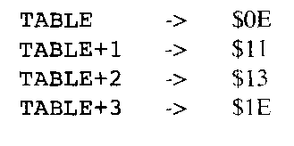
TABLE: DC.B 14,17,19,30 (4)
appearing in a program generates four consecutive bytes whose values are 14, 17, 19, and 30 and whose locations are at TABLE, TABLE+1, TABLE+2, and TABLE+3, as shown.

The actual value of the container TABLE will depend on where it is placed in the program. Note that, in contrast to the DS directive, this directive initializes or assigns values to the container (the address) as well as allocating room for its contents (the word at that address). Beware, however, that the contents are given this value only when the program is loaded into memory. If the program is rerun without being loaded again, the value of the contents is what was left there as a result of running the program the last time. When rerunning the program, you should check these values and possibly rewrite them before you assume they are the contents specified by the program.
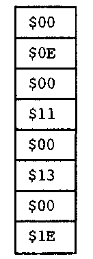
The DC. W (define constant word) directive does exactly the same thing as DC. B in (4) except that now two bytes are used for each value in the operand field, where, as usual, the high byte is first. For example, the directive
TABLE DC.W 14,17,19,30 (5)
puts the values in memory as shown.

The DC . L directive allocates and initializes a 32-bit memory block for each item in the directive’s operand list. Its mechanism is essentially like that for DC. W in (5).
The DC. B directive can have a sequence of ASCII characters in the operand field. (See Table 4.1 for a table of ASCII characters and their representations.) The ASCII codes for the characters are now put in the successive memory locations. The most convenient form is
![]()
where quotes enclose all the ASCII characters to be stored, namely, A, B, and C. Single quotes can be used instead of these quotes, especially where a character is a quote.
The define constant block DCB. B directive has a number n and a value v in the operand field; n copies of v are now put in’the successive memory locations. Suffixes .B, .W, and .L can be used in an obvious way, and . B is the default.
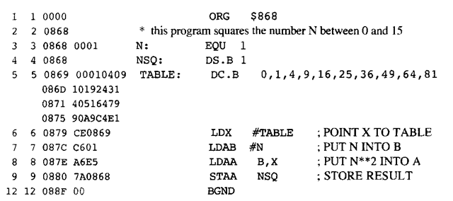
To see how these directives might be used, suppose that we wanted to store a table of squares for the numbers between 0 and 15. The program, whose assembler listing is shown in Figure 4.4, uses this table to square the number N, returning it as NSQ. With the given data structure, the location of N2 equals the location TABLE plus N. Thus if X contains the location TABLE and B contains the value of N, the effective address in the instruction LDAA B, X is the location of N2.

Figure 4A. Assembler Listing for the Program Square
