4.5
An assembler is really a simple program. To illustrate how it works and to gain valuable experience in assembly-language techniques, we write parts of a “Simple Assembler” SA1 for a simple computer, with the overall specifications shown in Figure 4.14. Figure 4.13a shows SAl’s machine code for a program to add two numbers (like Figure 1.5). and Figure 4.13b similarly shows how its source code might appear.
1. The target computer has only one 8-bit accumulator and 64 bytes of memory.
2. The target computer’s opcodes will be L (binary 00), A (01), and S (10), coded as bits 7 and 6 of the opcode byte, which have a 6-bit direct address coded in the low-order 6 bits of the opcode byte. The assembler has a directive D, for “define constant byte,” that has one two-digit hexadecimal number operand.
3. A source code line can have (1) a label and one space or else (2) two spaces. Then it has an opcode or assembler directive. Then it has a space and an operand, ending in a carriage return.
4. The assembler is to be run on the 6812 host. Assume the source code does not have errors. The source code will be stored in a constant ASCII string SOURCE, which is null terminated; and the object code, stored in 8-byte vector OBJECT, is indexed using an 8-bit variable LCNTR. No listing is produced.
5. All labels will be exactly one character long. The symbol table, stored in the 8-byte vector LABELS, consists of four 2-byte rows for each symbol, each row comprising a character followed by a one-byte address.
Figure 4.14. Simple Computer and Assembler SA1 Specifications
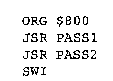
Figure 4.15. Assembler Main Program
The first instruction, which will be stored in location 0, loads the contents of location 3. The left two bits, the opcode, are 00, and the address of location 3 is 000011, so the machine code is 03 in hexadecimal. The next instruction’s opcode is 01 for add; its effective address is 000100. The last instruction’s opcode is 10 for store; its effective address is 000101. The source code shown in Figure 4.13b includes directives to initialize location 3 to $12, location 4 to $34, and location 5 to 0.
The assembler is written as two subroutines called PAS SI and PASS 2. This program segment illustrates the usefulness of subroutines for breaking up a large program into smaller subroutines that are easier to understand and easier to debug.
The data are defined by assembler directives, generally written at the beginning of the program. See Figure 4.16. They can be written just after the program segment shown in Figure 4.15. The first directive allocates a byte to hold the object pointer (which is the location counter). The second directive allocates and initializes the ASCII source code to be assembled. The next two lines allocate two eight-element vectors, which will store the machine code and symbol table.

Figure 4.16. Assembler Directives
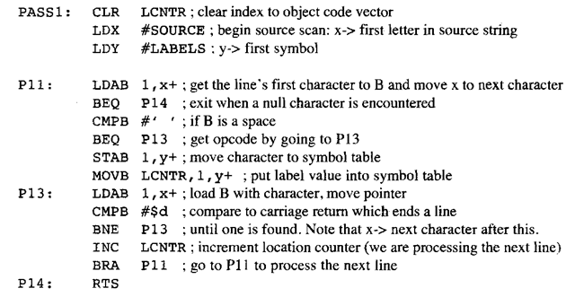
Figure 4.17. Assembler Pass 1
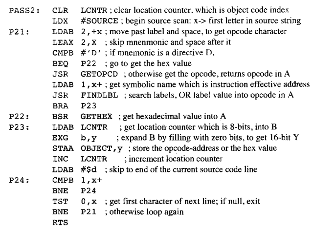
Figure 4.18. Assembler Pass 2
PASS1 (Figure 4.17) simply reads the characters from the source listing and inserts labels and their values into the symbol table. As is typical of many programs, an initial program segment initializes the variables needed in the rest of the subroutine, which is a loop. This loop processes one line of assembly-language source code. If the line begins with a label, it inserts the label and the current location counter into the symbol table. If the line begins with a space, it skips the character. It then scans the characters until it runs into the end of the line, indicated by a carriage return. Then it repeats the loop. When a NULL character is encountered where a line should begin, it exits.
PASS2 (Figure 4.18) simply reads the characters from the source listing and generates machine code, which is put into the object code vector. As in PASS1, an initial program segment initializes the variables needed in the rest of the subroutine, which is a loop. This loop processes one line of assembly-language source code. The program skips the label and space characters. If the mnemonic is a D for define constant, it calls a subroutine GETHEX to get the hexadecimal value; otherwise, it passes the opcode mnemonic to a subroutine GETOPCD that searches the list of mnemonic codes, returning the opcode. In the latter case, the subroutine FINDLBL finds the symbolic label, ORing its value into the opcode. The machine code byte is then put into the object code OBJECT.
GETOPCD (Figure 4.19) searches until it finds a match for the mnemonic. As it searches for a match in B, it generates the machine code in A. Because there are no errors in our source code, this extremely simple search procedure will always succeed in returning the value for the matching mnemonic. Because the directive D has been previously tested, if the opcode mnemonic is not an “L” or an “A” it must be “S.”
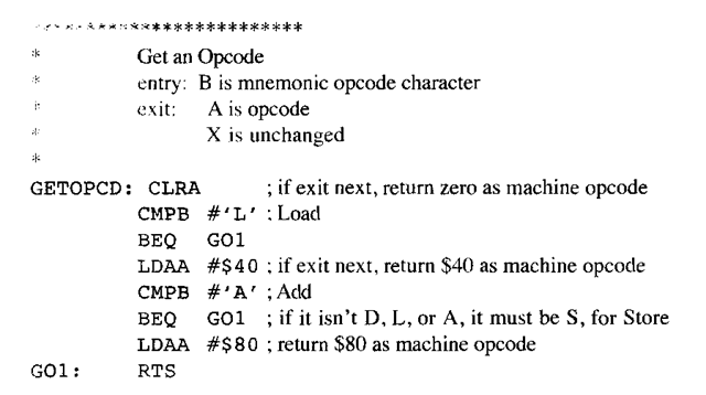
Figure 4.19. Subroutine to Get the Opcode
FINDLBL (Figure 4.20) begins by setting up X for a loop; the loop searches each row of the symbol table, which was created in PAS SI, until it finds a match. It searches each row of the symbol table. Because we assume there are no errors in our source code, it will always succeed in returning the value for the matching label.
GETHEX (Figure 4.21) calls an internal subroutine Gl to translate an ASCII character to a hexadecimal value. Gl uses the fact that ASCII letters “0″ to “9″ are translated into hexadecimal numbers by subtracting the character value of “0″ from them, and the remaining ASCII characters “A” to “F” are translated into hexadecimal by further subtracting 7 from the result (because there are seven letters between “9″ and “A” in the ASCII code). The first value obtained from the first letter is shifted to the high nibble and pushed on the stack. When the second value is obtained from the second letter, it is combined with the value pulled from the stack.
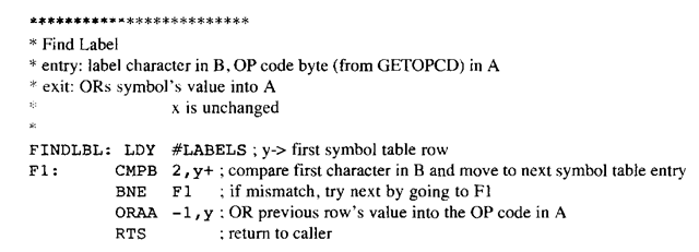
Figure 4.20. Subroutine to Insert a Label as an Operand
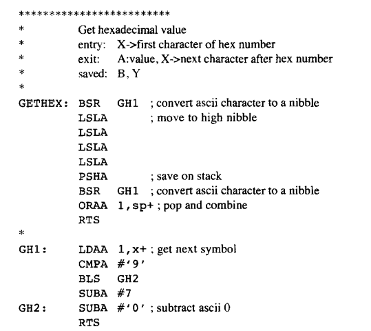
Figure 421. Convert ASCII Hex String to a Binary Number
The reader should observe that this subroutine, PASS2, is broken into subroutines GETOPCD, GETHEX, and FINLBL. Each of these subroutines is more easily understood and debugged than a long program PASS2 that doesn’t use subroutines. Each subroutine corresponds to an easily understood operation, which is described in the subroutine’s header. This renders the subroutine PASS2 much easier to comprehend.
The contents of the vector OBJECT will be downloaded into the target machine and executed there. The assembler permits the programmer the ability to think and code at a higher level, not worrying about the low-level encoding of the machine code.
The reader should observe the following points from the above example. First, the two-pass assembler will determine where the labels are in the first pass. Thus, labels that are lower in the source code than the instructions that use these labels will be known in the second pass when the instruction machine code is generated. Second, these subroutines further provide many examples of techniques used to convert ASCII to hexadecimal, used to search for matching characters, and used to insert data into a vector.
A Simplified Two-Pass Assembler (Microcontrollers)
Next post: Summary (Microcontrollers)
Previous post: Character String Operations (Microcontrollers)
