Introduction
Teleradiology is a routine practice for radiologists to make urgent diagnosis by remote viewing radiological images such as computed tomographic (CT), magnetic resonance (MR), computed radiographic (CR), and digital radiographic (DR) images outside their hospitals. Traditionally, due to limited network bandwidth and huge image file sizes, this technique was limited to fixed-point communication using an integrated services digital network (ISDN) and broadband network. Without any prior information, most radiologists would invariably require high-quality display units and lossless compressed images for their clinical diagnosis. Besides the technical issues involved in the uninterrupted provision of a 24hour teleradiology service, most hospital administrators have to consider a series of management issues on the quality of this service such as data confidentiality, integrity, and accessibility.
This article presents the implementation process of a high-quality teleradiology service using the third-generation (3G) wireless network. In the provision of this service, several high-quality notebook computers with a 15-inch liquid crystal display (LCD) screen of resolution 1,024 x 768 pixels and 32-bit color have been configured to view medical images in the digital imaging and communications in medicine (DICOM) format using a Web browser. These notebook computers are connected with 3G mobile phones so that users could access the Internet using Web browsers through the 3G network at a speed of at least 384 kbps. The users could also use the Web browser for logging into the hospital network through an application tunneling technique in a virtual private network (VPN). When logging into the VPN, for security purposes the network authentication is enhanced by a one-time and two-factor authentication (OTTFA) mechanism. In OTTFA, the user password contains two parts: a personal password and a randomly generated password. After successfully logging into the hospital network, the user has to log into the image server using another account name and password. The above are all important to ensure the high standard of confidentiality of the system.
The data volume of the image server is about 1 TB, stored in a level-5 configured redundant array of inexpensive disks (RAID). For management of this huge amount of data, the location of each image in the storage unit is stored in a Structural Query Language (SQL)-based database. Each image also has DICOM tags for storage of the patient name, identity (ID) number, study date, and time. After the success of each login, the user can query the image server for related images using the patient’s demographic data such as the study date. These are used to enhance the integrity of the system.
There are three image servers configured in a high available (HA) cluster using a load-balancing switch. The user could access any one of the servers for diagnostic purpose using the teleradiol-ogy technique. This setting is used to ensure the availability of the service 24 hours a day/7 days a week. The above system has operated for six months, and zero downtime was recorded. This leads to the belief that it is feasible to operate a quality teleradiology system using 3G networking technology with the important concerns of data confidentiality, integrity, and accessibility being dealt with in an effective manner.
background
Teleradiology is the process of sending radiologic images from one point to another through digital, computer-assisted transmission, typically over standard telephone lines, a wide-area network (WAN), or over a local area network (LAN). Through teleradiology, images can be sent to another part of the hospital or around the world.
In a hospital environment, it is not unusual that sometimes certain senior or experienced clinical staff would not be available onsite. These senior clinical staff may standby at home, on business trip, or just on their way to work. For urgent medical cases, remote consultation is required. It is important to have multimedia communication, including voice, text, and picture, between the senior clinicians and the hospital. A reliable, secure, easy-access, manageable, high-speed, standardized, multimedia medical consultation system is required.
PROBLEM
Today, teleradiology is still facing many limitations such as low network bandwidth, limited locations, and implementation issues associated with security, standards, and data management.
Limited Locations and Low Network Bandwidth
Depending on data-transfer rate requirements and economic considerations, images can be transmitted by means of common telephone lines using twisted pairs of copper wire, digital phone lines such as ISDN, coaxial cable, fiber-optic cable, microwave, satellite, and frame relay or T1 telecommunication links.
Today most teleradiology systems run over standard telephone lines. Over the next couple of years, we should see a substantial migration to switched-56 and ISDN lines, which offer higher speed and better line quality than standard dial-up phone lines. Other high-speed lines, including T1 and SMDS (shared multimegabit data services), will also become more popular as prices continue to drop.
However, remote consultation on fixed lines can only be performed in pre-installed locations such as a radiologist’s home. A wide-area wireless network can provide a more flexible teleradiology service for the users (Oguchi, Murase, Kaneko,
Takizawa, & Kadoya, 2001; Reponen et al., 2000; Tong, Chan, & Wong, 2003).
security in a 3G Network
The fragile security of 2.5G and 3G wireless applications was abundantly evident in Japan recently when malicious e-mails to wireless handsets unleashed a malevolent piece of code which took control of the communications device and, in some cases, repeatedly called Japan’s national emergency number. Other cell phones merely placed several long-distance calls without the user’s knowledge, while others froze up, making it impossible for subscribers to use any of the carrier’s services. Incidents like this and others involving spamming, denial of service (DoS), virus attacks, content piracy, and malevolent hacking are becoming rampant. The security breaches that have posed a constant threat to desktop computers over the last decade are migrating to the world of wireless communications where they will pose a similar threat to mobile phones, smart phones, personal digital assistants (PDAs), laptop computers, and other yet-to-be-invented devices that capitalize on the convenience of wireless communications
solutions standard
In 2003, the American College of Radiology (ACR) published a technical standard of telera-diology in which the DICOM standard (Bidgood & Horii, 1992) was used as a framework for medical-imaging communication. The DICOM standard was developed by the ACR and the National Electrical Manufacturers Association (NEMA) with input from various vendors, academia, and industry groups. Based upon the open system interconnect (OSI) reference model, which defines a seven-layer protocol, DICOM is an application-level standard, which means it exists inside layer 7. DICOM provides standardized formats for images, a common information model, application service definitions, and protocols for communication.
3G Network
3G stands for third generation (Collins & Smith, 2001) and is a wireless industry term for a collection of international standards and technologies aimed at increasing efficiency and improving the performance of mobile wireless networks (data speed, increased capacity for voice and data, and the advent of packet data networks vs. today’s switched networks). As second-generation (2G) wireless networks evolve into third-generation systems around the globe, operators are working hard to enable 2G and 3G compatibility and worldwide roaming, including WCDMA, CDMA2000, UMTS, and EDGE technologies. In this project 3G technology was applied in teleradiology service for improving the speed of communication.
Types of 3G
Wideband Code Division Multiple Access (WCDMA)
This is a technology for wideband digital radio communications of Internet, multimedia, video, and other capacity-demanding applications. WCDMA has been selected for the third generation of mobile telephone systems in Europe, Japan, and the United States. Voice, images, data, and video are first converted to a narrowband digital radio signal. The signal is assigned a marker (spreading code) to distinguish it from the signal of other users. WCDMA uses variable rate techniques in digital processing and can achieve multi-rate transmissions. WCDMA has been adopted as a standard by the ITU under the name IMT-2000 direct spread.
Code Division Multiple Access 2000 (CDMA 2000)
Commercially introduced in 1995, CDMA quickly became one of the world’s fastest-growing wireless technologies. In 1999, the International Telecommunications Union selected CDMA as the industry standard for new “third-generation” wireless systems. Many leading wireless carriers are now building or upgrading to 3G CDMA networks in order to provide more capacity for voice traffic, along with high-speed data capabilities. Today, over 100 million consumers worldwide rely on CDMA for clear, reliable voice communications and leading-edge data services.
Universal Mobile Telecommunication (UMTS)
This is the name for the third-generation mobile telephone standard in Europe, standardized by the European Telecommunications Standards Institute (ETSI). It uses WCDMA as the underlying standard. To differentiate UMTS from competing network technologies, UMTS is sometimes marketed as 3GSM, emphasizing the combination of the 3G nature of the technology and the GSM standard which it was designed to succeed. At the air interface level, UMTS itself is incompatible with GSM. UMTS phones sold in Europe (as of 2004) are UMTS/GSM dual-mode phones, hence they can also make and receive calls on regular GSM networks. If a UMTS customer travels to an area without UMTS coverage, a UMTS phone will automatically switch to GSM (roaming charges may apply). If the customer travels outside of UMTS coverage during a call, the call will be transparently handed off to available GSM coverage. However, regular GSM phones cannot be used on the UMTS networks.
Enhanced Data for Global Evolution (EDGE)
EDGE is a technology that gives GSM the capacity to handle services for the third generation of mobile telephony. EDGE was developed to enable the transmission of large amounts of data at a high speed, 384 kilobits per second. EDGE uses the same TDMA (time division multiple access) frame structure, logic channel, and 200 kHz carrier bandwidth as today’s GSM networks which allows existing cell plans to remain intact.
Image Resolution
Digital images, whether viewed on a computer monitor, transmitted over a phone line, or stored on a hard disk or archival medium, are pictures that have a certain spatial resolution. The spatial resolution, or size, of a digital image is defined as a matrix with a certain number of pixels (information dots) across the width of the image and down the length of the image. The more pixels, the better the resolution. This matrix also has depth. This depth is usually measured in bits and is commonly known as shades of gray: a 6-bit image contains 64 shades of gray; 7-bit, 128 shades; 8-bit, 256 shades; and 12-bit, 4096 shades.
The size of a particular image is referenced by the number of horizontal pixels “by” (or “times”) the number of vertical pixels, and then by indicating the number of bits in the shades of gray as the depth. For example, an image might have a resolution of 640 x 480 and 256 shades of gray, or 8 bits deep. The number of bits in the data set can be calculated by multiplying 640 x 480 x 8 equals 2,457,600 bits. Since there are 8 bits in a byte, the 640 x 480 image with 256 shades of gray is 307,200 bytes or .3072 megabytes of information.
Data compression
Although images should be permanently archived as raw data or with only lossless data compression (no data is destroyed), hardware and software technologies exist that allow teleradiology systems to compress digital images into smaller file sizes so that the images can be transmitted faster. Compression is usually expressed as a ratio: 3:1, 10:1, or 15:1. The compression ratio refers to the ratio of the size of a compressed file to the original uncompressed file.
Certain images can withstand a substantial amount of compression without a visual difference: computed tomography and magnetic resonance images have large areas of black background surrounding the actual patient image information in virtually every slice. The loss of some of those pixels has no impact on the perceived quality of the image nor does it significantly change reader-interpretive performance.
Image Transmission
Image-transmission time is directly proportional to the file size ofthe digital image. The greater the amount of digital information in an image which involves the image matrix size and the number of bits per pixel, the longer the time required to transmit the image from one location to another. A radiological image contains a large amount of digital information. For example, an image with a relatively low resolution of 512 x 512 x 8 bits contains 2,097,152 bits of data, and a 1,024 x 1,024 x 8-bit image has 8,388,608 bits of data. Transmission time has to follow the laws of size. The only way to decrease the transmission time is either to increase the speed of the modem or reduce the number of bits (compress the image) being sent. The following formula is used to calculate the time to transmit an image:
(Matrix Size) x (Matrix Depth + 2 bits) x (Percentage of Compression) / (Modem Speed) = Seconds to Transmit
Matrix Depth is the shades of gray as shown in Table 1.
For modem or router control, most devices add 2 bits when transmitting as overhead.
Data Management
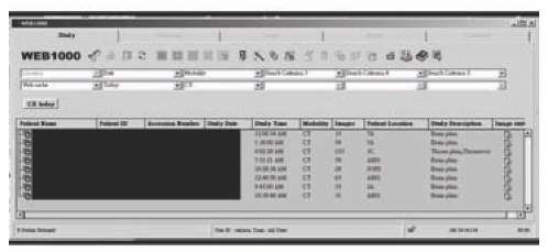
According to the ACR Technical Standard for Teleradiology, each examination data file must have an accurate corresponding patient and examination database record that includes patient name, identification number, examination date, type of examination, and facility at which the examination was performed. A Structural Query Language (SQL) database has been installed for the registration of each incoming and query of studies.
Web Technology
Web technology offers a significant advantage to physicians who need to receive images quickly,and who require real-time image navigation and manipulation to perform diagnostic tasks effectively. It facilitates the use of graphical-user interfaces, making teleradiology and picture achieving and communication system (PACS) applications easier to use and more responsive. Additionally, clients and servers can be run on different platforms, allowing end users to free themselves from particular proprietary architectures. Software applications designed for client-server computing can interface seamlessly with most hospital information systems (HISs) (RCR, 1999) or radiology information systems (RISs), while providing rapid soft-copy image distribution.
Table 1. Shades of gray and matrix depth
|
Shades of Gray |
Matrix Depth |
Shades of Gray |
Matrix Depth |
|
256 |
8 bits |
16 |
4 bits |
|
128 |
7 bits |
8 |
3 bits |
|
64 |
6 bits |
4 |
2 bits |
|
32 |
5 bits |
2 |
1 bit |
Storage
RAID (Marcus & Stern, 2003) stands for redundant array of inexpensive (or identical) disks. RAID employs a group of hard disks and a system that sorts and stores data in various forms to improve data-acquisition speed and provide improved data protection. To accomplish this, a system of levels (from 1 to 5) “mirrors,” “stripes,” and “duplexes” data onto a group of hard disks. All images were stored in the RAID of the server for high availability of the service.
Display
Today, most of the gray shades were produced by a mixing of primary colors in the video boards. Three types of video boards are commonly available, including 16-bit, 24-bit, and 32-bit color video cards. The video board with higher bits can be configured in a lower bit mode. The 16-bit color mode is called “High Color” mode with almost “good enough” quality to show photo images, at least for most purposes; 16-bit color is 5 bits each of red, green, and blue packed into one 16-bit word (2 bytes per pixel). Five bits can show 32 shades of each primary RGB channel, and 32 x 32 x 32 is 32K colors. Green used the extra one bit for 6 bits to achieve 64K colors overall, but half of them are green. The human eye is most sensitive to green-yellow, and more shades are a bigger advantage there. Green has twice the luminance of red and six times more than blue, so this is very reasonable. Video boards do vary, but 24 bits is normally not so much better in most cases, except in wide smooth gradients.
Video boards for the last few years are 24-bit color or “true color”; 24-bit color is 8 bits each of RGB, allowing 256 shades of each primary color, and 256 x 256 x 256 = 16.7 million color combinations. Studies show that the human eye can detect about 100 intensity steps (at any one current brightness adaptation of the iris), so 256 tones of each primary is more than enough. We would not see any difference between RGB (90,200,90) and (90,201,90), but we can detect 1% steps (90,202,90) (on a cathode ray tube (CRT) tube, but 18-bit LCD panels show 1.5% steps). So our video systems and printers simply do not need more than 24 bits.
Theoretically, there is no true 32-bit color display mode. The confusion is that 24-bit color mode normally uses 32-bit video mode today, referring to the efficient 32-bit accelerator chips (word size). The 24-bit color mode and so-called 32-bit video mode show the same 24-bit colors, the same 3 bytes RGB per pixel; 32-bit mode simply discards one of the four bytes (wasting 25% of video memory), because having 3 bytes per pixel severely limits video acceleration functions. Processor chips can only copy data in byte multiples (8, 16, 32, or 64 bits). A 24-bit copy done with a hardware video accelerator would require three 8-bit transfers per pixel instead of one 32bit transfer; 32-bit video mode is for speed, and it shows 24-bit color.
Liquid crystal Display (lcd)
In teleradiology, it is more convenient to use LCD for image display than CRT. In LCD, there are no CRTs. Instead, thin “sandwiches” of glass contain liquid-crystal filled cells (red, green, and blue cells) that make up a pixel. Arrays of thin film transistors (TFTs) provide the voltage power, causing the crystals to untwist and realign so that varying amounts of light can shine through each, creating images. This particular sensitivity to light makes LCD technology very useful in projection such as LCD front projectors, where light is focused through LCD chips.
Specifically, there are five layers to the LCD display: a backlight, polarized glass sheet, colored pixel layering, coating of liquid crystal solution that responds to signals off a wired grid of x and y coordinates, followed by a second glass sheet. To create an image, electrical charges, precision coordinated in various degrees and volts, effect the orientation of the liquid crystals, opening and closing them and changing the amount of light that passes through specific colors of pixels. LCD technology has increased its accuracy that can produce sharp and more accurate color images than earlier passive-matrix technologies.
One-Time and Two-Factor Authentication
OTTFA is an authentication protocol that requires two independent ways to establish identity and privileges in which at least one is continuously and non-repetitively changing. This contrasts with traditional password authentication, which requires only one factor such as the knowledge of a password in order to gain access to a system. OTTFA technique provides a secure authentication protocol for the teleradiology service.
Application Tunneling (Port Forwarding)
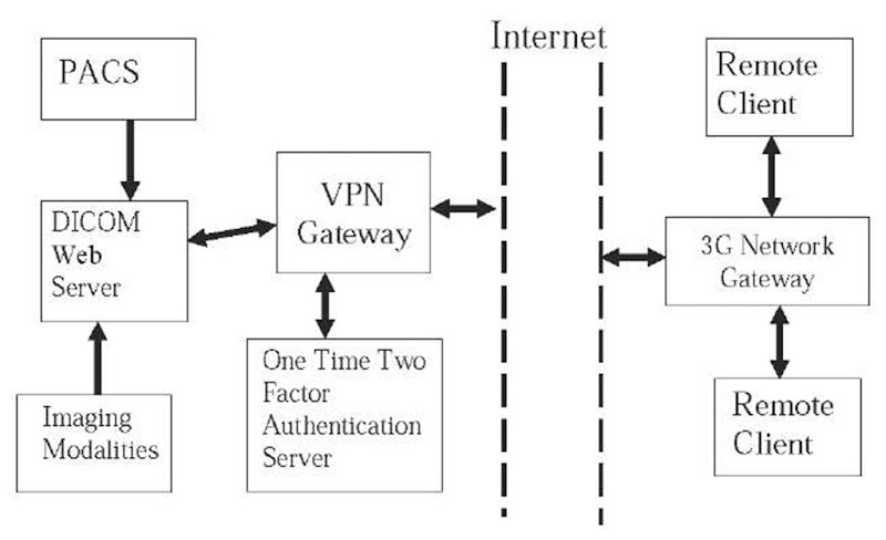
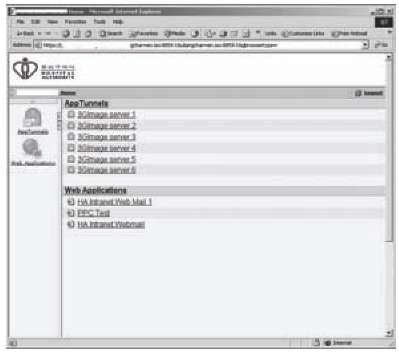
Application tunneling (or port forwarding) is a combination technique of routing by port combined with packet rewriting. A convention router examines the packet header and dispatches the packet on one of its other interfaces, depending on the packet destination address. Port forwarding examines the packet header and forwards it on to another host with the header rewriting depending on the destination port. The application of application tunneling is its inability of the destination machine to see the actual originator of the forwarded packets and instead seeing them as originating from the router. One of the applications of application tunneling is in a virtual private network gateway, as shown in Figure 1. Using the application tunneling technique, the security of the teleradiology system can be strengthened considerably.
Figure 1. Schematic diagram of 3G wireless medical image viewing system
High Available Server cluster
The purpose of high available (HA) clustering is to maintain a non-stop teleradiology service for the users. In the current design, there are three image servers configured to form an HA cluster using a load-balancing switch. The user could access any one of the servers for making of diagnosis using the teleradiology technique. Other clustering techniques being used include operating system clustering, Internet protocol (IP) failover, and fault tolerance (FT) techniques.
Implementation Result
The overall design of the 3G wireless medical image viewing system is shown in Figure 1. The medical images received from the PACS or imaging modalities were stored in the DICOM Web server.
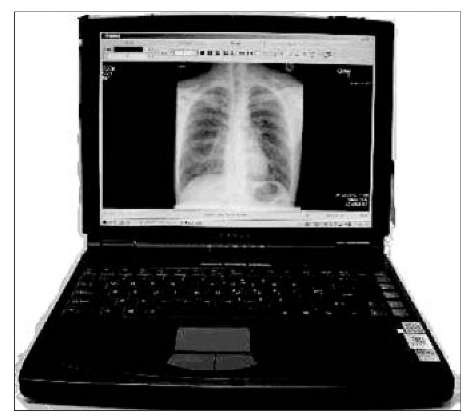
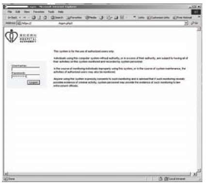
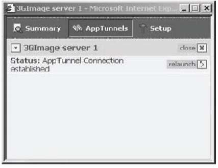
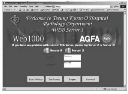
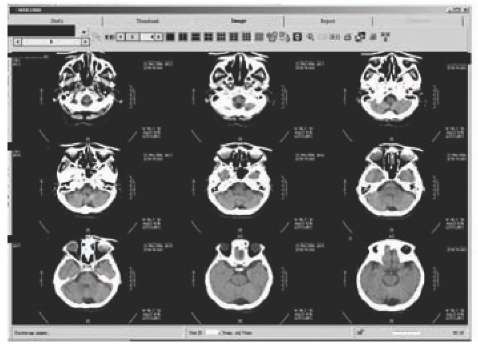
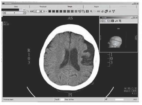
The operation of the system is shown in Figures 2 through 10. The users can use a laptop computer as a remote client for the connection to the Internet through a 3G network gateway provided by their service provider (see Figure 2). From the Internet, the users can make a connection to the VPN gateway and be authenticated by the OTTFA server. After login, the VPN gateway will redirect the user to the DICOM Web server using the application tunneling technique. After another login of the DICOM Web server, users can query the server for related studies. Finally, once the related studies are found and selected, all related images can be retrieved and displayed as shown in Figures 9 and 10.
FUTURE TRENDS
4G Wireless Network
4G is the next generation of wireless networks that will replace 3G networks sometimes in future. In another context, 4G is simply an initiative by academic R&D laboratories to move beyond the limitations and problems of 3G to meet its promised performance and throughput. In reality, as of the first half of 2002, 4G is a conceptual framework for or a discussion point to address future needs of a universal high-speed wireless network that will interface with the wireline backbone network seamlessly. 4G also represents the hope and ideas of a group of researchers at Motorola, Qualcomm, Nokia, Ericsson, Sun, HP, NTT DoCoMo, and other infrastructure vendors who must respond to the needs of MMS, multimedia, and video applications if 3G never materializes in its full glory.
Figure 2. A laptop computer for teleradiology
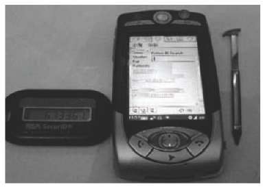
Figure 3. A One-Time Two-Factor Authentication device with a 3G phone for teleradiology
Figure 4. Login screen of VPN gateway
Figure 5. Successful login of VPN gateway
Figure 6. Application tunneling screen
Figure 7. Connection to DICOM Web server established
Figure 8. Image data management
Figure 9. Selection of images
Figure 10. Viewing of images
A comparison of key parameters of 4G with 3G is as shown in Table 2.
conclusion
The above-mentioned 3G wireless medical image viewing system is providing a transfer speed of 384 kbps, which is comparable to a T1 fixed line of a speed of 1.4 mbps, but with greater accessibility and confidentiality. This system has been used successfully to ensure the availability of the teleradiology service 24 hours a day and 7 days a week. Throughout its construction and operation, it is found that the ACR and DICOM standards have provided useful guidelines on achieving the quality assurance and integrity expectations of this kind of service.
KEY TERMS
Application Tunneling: A combination technique of routing by port combined with packet rewriting.
Digital Imaging and Communication in Medicine (DICOM): A standard developed by the American College of Radiology (ACR) and the National Electrical Manufacturers Association (NEMA) to provide standardized formats for images, a common information model, application service definitions, and protocols for communication.
One-Time Two-Factor Authentication: An authentication protocol that requires two independent ways to establish identity and privileges in which at least one is continuously and non-repetitively changing.
Port Forwarding: Another name for application tunneling.
Redundant Array of Inexpensive (or Identical) Disks (RAID): Employs a group of hard disks and a system that sorts and stores data in various forms to improve data-acquisition speed and provide improved data protection.
Teleradiology: The process of sending radio-logic images from one point to another through digital, computer-assisted transmission, typically over standard telephone lines, a wide-area network (WAN), or over a local area network (LAN)
