The purpose of the HM is to provide campus users access to IPv6-based applications, even though parts of the campus might not have IPv6 support. Because of this lack of support, most of the campus network in the HM is IPv4-only. The IPv6 part of the campus network begins in the core layer. The following sections show the core layer configuration as well as the basic ISATAP configuration on the host. As mentioned previously, the HM uses dual-stack from the core layer into the data center. Those configurations are not relevant to the HM because the configurations are the same as those in the DSM. As with the DSM implementation section, configuration snippets for each aspect of the deployment are shown in these sections.
Network Topology
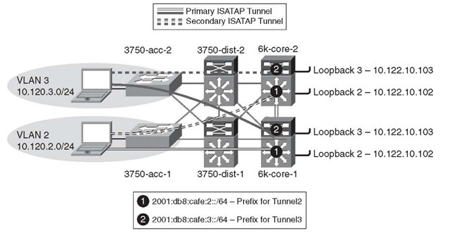
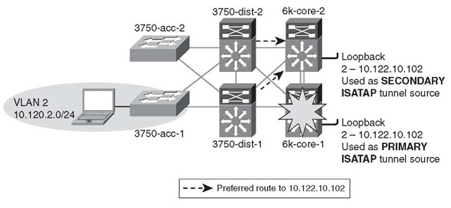
One difference in the HM topology is that the distribution layer is using a pair of Catalyst 3750 switches instead of the Catalyst 6500. This change is not because of any particular issue or recommendation; it is just the way the test lab is configured. Although the Catalyst 3750 does support IPv6 unicast forwarding in hardware, no IPv6 functionality is enabled so that it can simulate an IPv4-only platform for the sake of illustrating the HM configuration. Figure 6-15 shows the network topology for the HM.
Figure 6-15 Hybrid Model Network Topology
The topology is focused on the IPv4 addressing scheme in the access layer (used by the host to establish the ISATAP tunnel), core layer (used as the termination point by the host for ISATAP), and also the IPv6 addressing used for the ISATAP tunnel prefix. In the HM, the core-to-core links and the core-to-data center links are dual-stack. The IPv6 addressing is not shown for these links because they use the same configuration as the DSM. The configuration shows that the ISATAP access high availability is accomplished by using redundantly configured loopback interfaces that share the same IPv4 address between both core switches. To maintain prefix consistency for the ISATAP hosts in the access layer, the same prefix is used on both the primary and backup ISATAP tunnels.
Physical Configuration
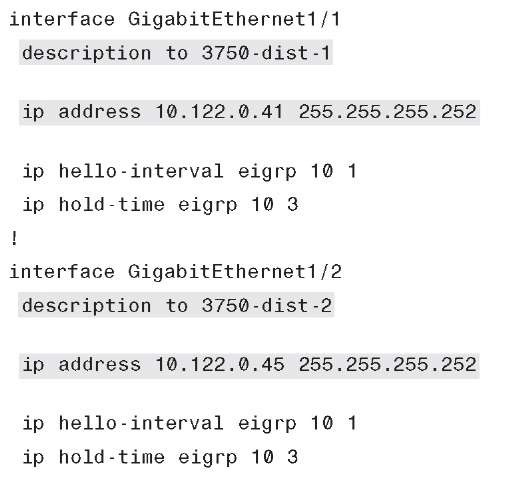
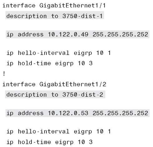
The configurations for both core layer switches are shown and include only the distribution-facing interfaces. These configurations are shown only for reference because their addressing can help you when the ISATAP high-availability validation output is shown. Note that everything between the access and core layers is IPv4-only, so nothing special is required other than a redundant and fast-converging IPv4 network.
Example 6-28 shows the 6k-core-1 configuration for the core-to-distribution links.
Example 6-28 6k-core-1 Interface Configuration
Example 6-29 shows the 6k-core-2 configuration for the core-to-distribution links.
Example 6-29 6k-core-2 Interface Configuration
Tunnel Configuration
The ISATAP configuration at the tunnel level is relatively straightforward, but the potentially confusing part relates to the high-availability design for the ISATAP tunnels. The basic configuration of ISATAP on a host consists of enabling IPv6 and configuring the ISATAP router name or IPv4 address. By default, Microsoft Windows XP, Vista, and Windows 7 perform a DNS query of "isatap.domain.com," where "domain.com" is the assigned domain name. If a DNS "A" record for "isatap" has been configured, the host begins to establish an ISATAP tunnel to the address resolved in the record. This default configuration works fine until something happens to the ISATAP router or the path to that router and the end systems have to find the alternate ISATAP router. All the configurations discussed in this topic include the ability to provide fault tolerance of IPv6 services as optimally as possible.
Providing high availability for ISATAP is crucial in the HM environment. Several methods provide redundancy of the ISATAP routers. The method discussed in the HM implementation uses the two core layer switches to provide fast failover of the ISATAP tunnels. The other method commonly used relies on DNS. Although the DNS method is faster to implement, it is also the most limiting in the overall IPv6 campus design and is the slowest for failover.
You must ensure that the tunnel destination (from the host point of view) is redundant across both core switches and ensure that both IPv4 and IPv6 routing is configured properly.
Two questions commonly asked are, Should there be deterministic routing from the distribution layer (IPv4) to one ISATAP router? Also, is there any value in load balancing? The following considerations apply:
■ The only host operating systems that support the outbound load balancing of ISA-TAP tunnels are Microsoft Windows Vista and Windows 7.
■ Using customer deployments and detailed testing as a baseline, it has been found that there are few to no benefits in load balancing ISATAP hosts to the ISATAP routers. Testing shows that load balancing from the host side when using redundant IPv6 prefixes for the ISATAP tunnels causes return routability issues, meaning that the return traffic does not take the same return path as the traffic that was sent. The core layer switches in this example can take the load for all the ISATAP tunnels in this design. If the primary core layer switch fails, the secondary can take all the tunnels with no issue. Load balancing in this design provides no improvement in performance, load, or availability and further complicates the management for the operator because troubleshooting the flow of traffic for ISATAP is made even more difficult. Implementing a design that is deterministic for ISATAP eases the burden of traffic management and troubleshooting as well as eliminates the return routability issues.
To maintain low convergence times for ISATAP tunnels when a core layer switch fails, it is important to provide redundant and duplicated tunnel addressing across both core switches. When this duplication is done, only one ISATAP router address or name is needed on the host, and DNS round-robin is not required. The following steps describe this process:
Step 1. Configure both core layer switches with the same loopback address (for example, 10.122.10.102). Loopback interfaces are used for their stable state and are perfect for tunnel termination. Take care in ensuring that this address is not used as the Router ID (RID) because you will have duplicate RID issues and will also impact CEF.
Step 2. Configure both core layer switches with a single ISATAP tunnel that uses the loopback as a source (for example, Loopback2—10.122.10.102). The ISATAP
IPv6 prefix is the same on both switches, so it does not matter which switch the host is terminated on; it uses the same prefix for connectivity. This lack of state is a critical element for fast convergence. If the host has to obtain a new prefix for each failover, the recovery time is impacted for this address process. Also, the client keeps all past (old ISATAP prefix) and new IPv6 addresses for the duration of their lifetimes. Using a single prefix for all ISATAP connections for the host greatly reduces convergence time for the host and allows a single IPv6 address entry for ISATAP in any failure scenario.
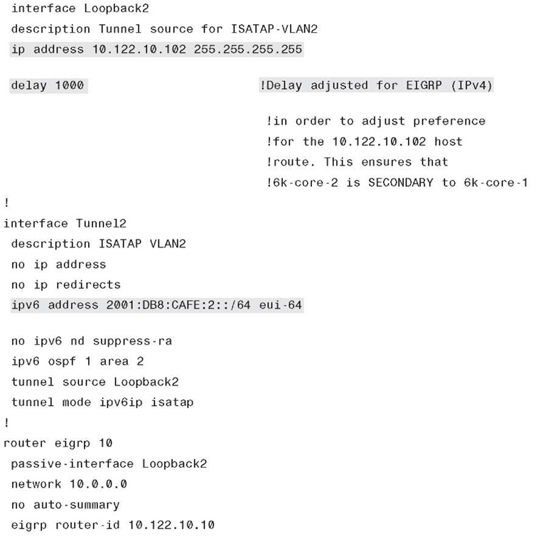
Step 3. Configure both core layer switches to advertise the loopback address through the IPv4 IGP. The primary switch (6k-core-1) uses default IGP metrics for the loopback address. The secondary switch (6k-core-2) alters the IGP metric (delay value on EIGRP) to make the loopback address on this switch be less preferred. Cisco recommends having a deterministic flow for the tunnels because load balancing between the tunnels using the same prefix is not desirable.
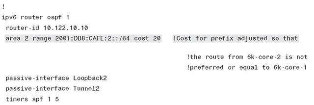
Step 4. Configure both core layer switches to advertise the ISATAP IPv6 prefix through the IPv6 IGP. The primary switch (6k-core-1) uses the default IGP metrics for the IPv6 prefix on the ISATAP tunnel. The secondary switch (6k-core-2) alters the IGP metric (cost value on OSPFv3) to make the ISATAP prefix on this switch be less preferred. This configuration is optional. It is used in this document because a deterministic flow for both IPv4 (see Step 3) and IPv6 is desired.
Step 5. Configure the host with a manually defined ISATAP router address or name (which correlates to a DNS "A" record).
Note In this section, EIGRP is used as the IGP for IPv4 and OSPFv3 is used as the IGP for IPv6. Using OSPF for both IPv4 and IPv6 or EIGRP for both versions is fully supported. EIGRP for IPv6 was shown in the DSM, and to give the reader a look at OSPFv3 configurations, it has been included here as reference.
To keep the ISATAP tunnels, HA, and routing configurations simple to understand, they are shown together. For the sake of simplicity, the only configuration shown is that of the tunnels for VLAN2. The tunnels for VLAN3 are the same except for addressing specifics.
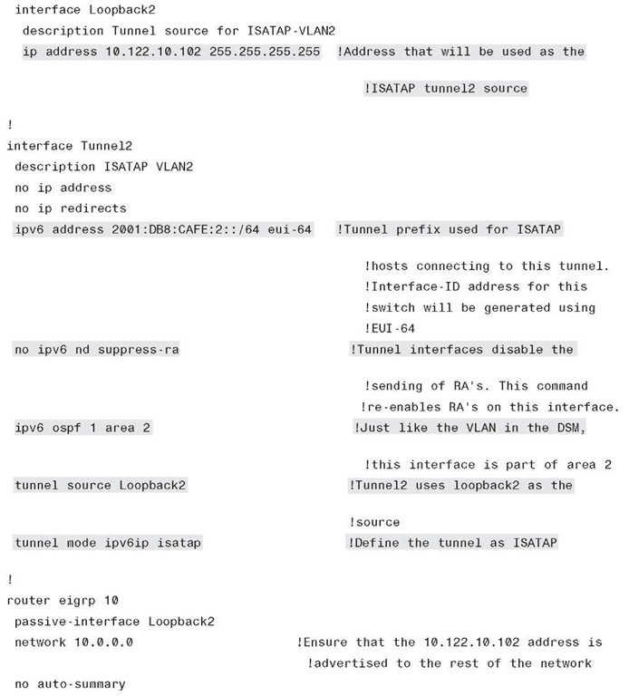
The following configurations illustrate the preceding five steps described. The configuration is comprised of a loopback interface that is used as the ISATAP tunnel source on 6k-core-1. The tunnel interface has an IPv6 address defined and an OSPFv3 configuration. The IGP definition is not used to establish adjacency through the tunnel but is used to advertise the IPv6 prefix of the tunnel interface. By default, on tunnel interfaces, router advertisements are not sent on tunnels because they are point-to-point, and normally there is no reason to send an RA. However, ISATAP is a semiautomatic multipoint tunnel, which implies that both ends of the tunnel are not known. Because of this somewhat dynamic process, you must disable RA suppression (enable RAs). Again, in this example, EIGRP is used for IPv4 and OSPFv3 for IPv6. You must advertise the IPv4 address of the loopback so that clients can reach the interface for tunnel connectivity. Similarly, the IPv6 ISATAP tunnel prefix must be advertised to the rest of the IPv6-enabled network.
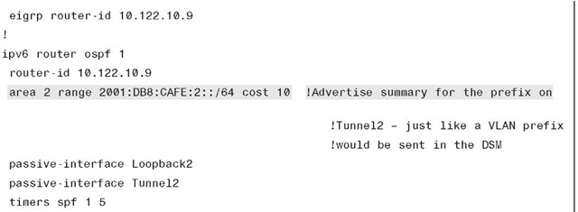
Example 6-30 shows the 6k-core-1 ISATAP configuration. Again, a loopback is configured and is used as the anchor for the ISATAP tunnel. The tunnel definition needs to have an IPv6 address configured, default suppression of RAs on tunnel interfaces is disabled (we want RAs sent), an IGP is enabled to advertise the IPv6 prefix to the rest of the network, and the tunnel source (loopback) and mode are defined.
Example 6-30 6k-core-1 ISATAP Configuration
Example 6-31 is basically the same configuration with the exception of unique IPv4 and IPv6 addressing. Also, the IGPs are tuned so that the 6k-core-2 switch is less favorable as a path to the ISATAP tunnel interface.
Example 6-31 6k-core-2 ISATAP Configuration
Example 6-31 6k-core-2 ISATAP Configuration
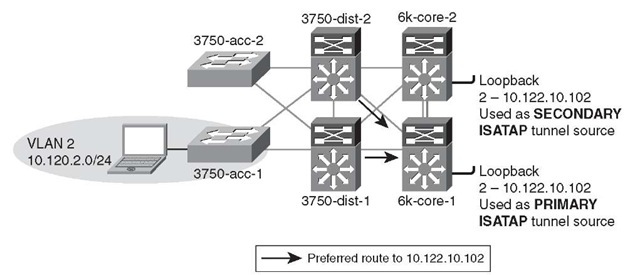
Figure 6-16 shows the IPv4 routing view from the distribution layer switches to the ISATAP tunnel’s interfaces (loopbacks on core switches). Loopback2 on 6k-core-1 is set as the primary ISATAP router address for the host. As shown in the previous IPv4 IGP configuration, 6k-core-2 is configured to have the host route of 10.122.10.102 have a higher delay and therefore is not preferred. When a packet arrives from the host in VLAN2 for the ISATAP router (10.122.10.102), a lookup is performed in the distribution layer switch for 10.122.10.102 and the next hop for that address is 6k-core-1.
Figure 6-16 Hybrid Model – Preferred Route for 6k-core-1
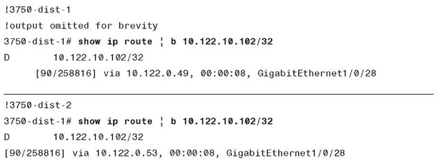
The routing table entry for 10.122.10.102 on the 3750-dist-1 switch is shown in Example 6-32. There is a single entry for 10.122.10.102, which is learned through 10.122.0.41 (6k-core-1).
Example 6-32 3750-dist-1 IPv4 Route Output – Path to Core
The router table entry on the 3750-dist-2 switch also shows a single route for 10.122.10.102 with a next hop of 10.122.0.45 (6k-core-1), as shown in Example 6-33.
Example 6-33 3750-dist-2 IPv4 Route Output – Path to Core
Figure 6-17 shows that 6k-core-1 has failed, and therefore the route to Loopback2 (10.122.10.102) is no longer available. When the 6k-core-1 route is removed, the new route for 10.122.10.102 is used and packets are then forwarded to 6k-core-2.
Figure 6-17 Hybrid Model – Preferred Route 6k-core-2 After Failure
The updated routing table entry for 10.122.10.102 on the distribution layer switches shows that there is now a change in the routing entry with a next hop of the 6k-core-2 switch (see Example 6-34).
Example 6-34 3750-dist-1 IPv4 Route Output – Post 6k-core-1 Failure
The following two ways enable the host for ISATAP communication in the HM environment:
■ Manual definition of the ISATAP IPv4 router address
■ Manual definition of the ISATAP IPv4 DNS name (requires DNS record entries)
Using the ISATAP IPv4 router address method is straightforward but difficult to scale without some kind of script or host management tools. As previously mentioned, various tools such as Microsoft Group Policy, Windows PowerShell, and Microsoft SMS Server can be used to run the command locally on the host at login or another predetermined time.
On the Microsoft Windows host in VLAN 2, ISATAP is enabled and the IPv4 ISATAP router address is defined (IPv6 is enabled by default on Windows Vista and 7). As previously mentioned, the HM design maps the host in a VLAN/subnet to a specific ISATAP router address. This configuration is not a requirement but it is recommended if the existing security policy enforces ACLs based on the source IP address of a given VLAN.
Here the host is in VLAN 2, which is in the 10.120.2.0/24 subnet and is therefore configured to use the ISATAP router of 10.122.10.102, where the 2 in 102 signifies VLAN or subnet 2. The same would happen for VLAN 3 or 10.120.3.0/24, where the ISATAP router is 10.122.10.103. The following configuration is through the netsh command interface on the Microsoft Windows client and is used to manually set the ISATAP router:
The command in Example 6-35 can be used to verify that the address has been accepted. Example 6-35 Microsoft Windows NETSH Output for ISATAP Router – Address
The host has successfully established an ISATAP connection to the primary core layer switch (6k-core-1) and received a valid prefix 2001:db8:cafe:2:0:5efe:10.120.2.101 (through an RA—DHCPv6 is not used with ISATAP). ISATAP uses the IPv4 address on the host as the rightmost 32-bit portion of the 64-bit interface ID. ISATAP "pads" the leftmost 32 bits of the 64-bit interface ID with 0000:5efe or 0200:5EFE (if using public unicast IPv4 addresses). The IPv4 address (10.120.2.101), which is assigned to the host through DHCP (or could be static), is used as the tunnel source on the host side of the tunnel, and Loopback2 (10.122.10.102) on the core layer switches is used as the tunnel destination (previously configured ISATAP router address) for the host.
The tunnel adapter automatic tunneling the pseudointerface is as shown in Example 6-36.
Example 6-36 Microsoft Windows IPv6 Address Summary
Using the ISATAP IPv4 router name method is also straightforward but requires DNS entries. If separation of host-to-ISATAP tunnels is desired, such as the configuration described in the previous example, it is difficult to scale, even with DNS, without some kind of script or host management tools. As previously mentioned, various tools such as Windows PowerShell and Microsoft SMS Server can be used to run the command locally on the host at time of login or another predetermined time. Group Policy can also be used as a means to set the ISATAP values.
In this example, a name is used for the ISATAP router instead of an ISATAP IPv4 address. The default DNS name that ISATAP tries to resolve is "isatap" along with the domain suffix. For example, if this host is in domain "cisco.com," the host attempts to resolve "isat-ap.cisco.com." The user can alter this name similarly to altering the address selection. The configuration on the Microsoft Windows host shown in Example 6-37 shows that the name "vlan2-isatap" has been used as the DNS name.
Example 6-37 Microsoft Windows NETSH Output for ISATAP Router – DNS
On the DNS server, the following entries were made for the two VLANs shown in this section:
■ vlan2-isatap: Host (A) 10.122.10.102
■ vlan3-isatap: Host (A) 10.122.10.103
