Cisco Virtual Switching System with IPv6
This section gives descriptions and examples of using the Cisco Virtual Switching System (VSS) with IPv6 in the campus.
Most enterprise networks deploy switches in pairs at the distribution and core layer to provide high availability in cases of chassis failure. The challenges of this design are that it increases the number of network management points (network nodes) as well as requires running protocols like Spanning Tree Protocol (STP) and HSRP. Additionally, to have a loop-free topology, STP blocks half of the links going to the access layer switches, leading to inefficient use of bandwidth.
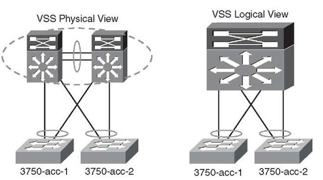
VSS solves these challenges by combining a pair of Catalyst 6500 series switches into a single network/management element. VSS looks like a single logical switch to the peer switches (see Figure 6-13). Peering switches (that is, access/core switches) connect to the two physical chassis used in a VSS pair with a single ether-channel, called MEC (Multi-chassis Ether-channel). The MEC allows the network designer to come up with a redundant but loop-free Layer 2 network topology without using protocols like STP and HSRP.
Figure 6-13 VSS Physical and Logical Views
The two switches in VSS are in an active-active mode from a data-plane perspective and active-standby mode from a control-plane perspective. In case of failure of one of the chassis, the active-active data-plane model keeps the traffic forwarding intact while the control plane is converging.
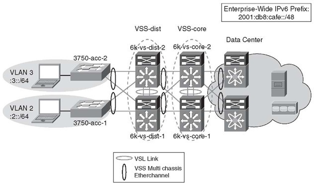
Figure 6-14 shows a deployment of VSS using most of the previously discussed DSM topology; only now, the core and distribution layers are using VSS.
Figure 6-14 VSS with IPv6 Deployment – Distribution/Core
From a logical network perspective, the topology appears as a chain of single switches when in reality they are deployed in physical pairs. Other than the loop-free Layer 2 capability and the singular logical configuration of VSS, all other elements of DSM for the distribution and core layers apply.
From a redundancy perspective, the VSS provides stateful switchover (SSO) across the chassis, so in the case of a failure with a single chassis in a VSS pair, peering switches see the failure as a link failure in the MEC and not a topology change. This results in the surviving chassis forwarding the traffic. Additionally, because the switchover across the chassis was SSO, there is no need for routing protocol reconvergence because the routing topology remains intact.
The same IPv6 addressing that was used in the previous DSM examples is used here. One difference with VSS and IPv4 and IPv6 addressing is that each VSS pair uses one address versus one per chassis in a non-VSS configuration. Table 6-5 illustrates the IPv6 addressing used in the VSS example configurations.
Table 6-5 Switch Loopback/VLAN Addressing for VSS Example
|
Switch |
Interface |
IPv6 Address |
|
VSS-dist |
Loopback |
2001:db8:cafe:1f3::3/128 |
|
VLAN2 |
2001:db8:cafe:2::2/64 |
|
|
VLAN3 |
2001:db8:cafe:3::2/64 |
|
|
VSS-core |
Loopback |
2001:db8:cafe:1f3::1/128 |
VSS Configuration
VSL (Virtual Switch Link) is the technology behind the VSS. The VSS pair exchanges configuration and state information across the VSL. The standby chassis monitors the active chassis over the VSL.
To form a VSS, two standalone switches need to follow the standalone-to-VSS conversion process. The following summarizes the three-step conversion process:
Step 1. Choose a virtual switch domain number (unique in the same Layer 2 network).
Step 2. Choose a switch number for each of the switches (in the example, switch #1 for 6k-vs-dist-1 and switch #2 for the 6k-vs-dist-2).
Step 3. Choose a VSL link (ports connecting the two switches with a unique ether-channel number on each side).
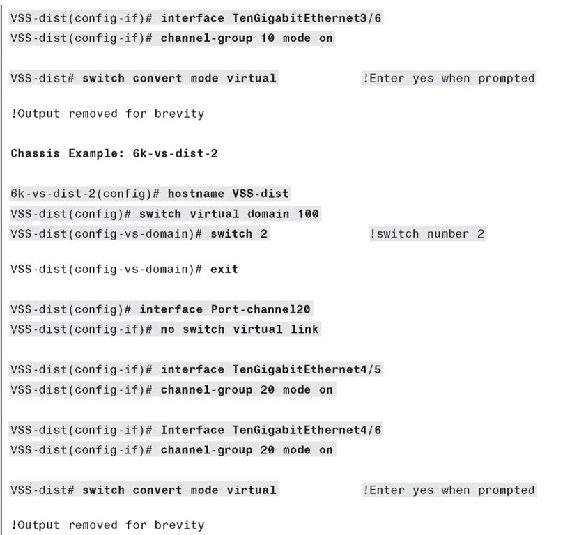
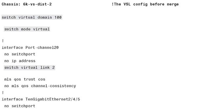
The frames over the VSL link are encapsulated with a special 32-byte header that provides information for the VSS to forward the packet on the peer chassis. The VSL link carries the control and data; the following configuration example uses port-channel 10 and 20 on the two sides of the VSL link. The VSL-specific configuration after the conversion is shown in Example 6-23.
Example 6-23 Conversion to VSS (6k-vs-dist-1 and 6k-vs-dist-2)
Example 6-23 Conversion to VSS (6k-vs-dist-1 and 6k-vs-dist-2)
Note For details about the conversion from a standalone to a virtual switch, refer to the Migrate Standalone Cisco Catalyst 6500 Switch to Cisco Catalyst 6500 Virtual Switching System documentation at http://www.cisco.com/en/US/products/ps9336/ products_tech_note09186a0080a7c74c.shtml.
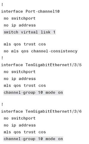
After the conversion to VSS, the configuration on each of the distribution switches is as shown in Example 6-24.
Example 6-24 Distribution Switch VSL Configuration (6k-vs-dist-1)
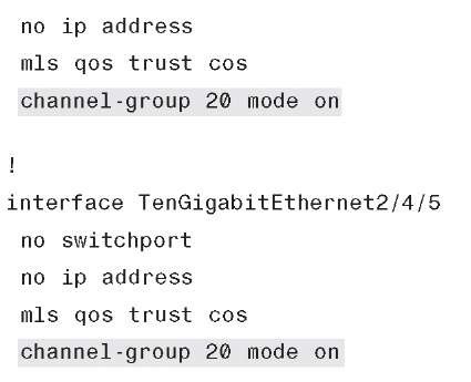
After the conversion to VSS, when both switches come up, the VSL-specific configuration shown in Example 6-25 will be dynamically merged, resulting in the same configuration on both switches.
Example 6-25 Distribution Switch VSL Configuration (6k-vs-dist-2)
Example 6-25 Distribution Switch VSL Configuration (6k-vs-dist-2)
Note In VSS, the interface naming convention has an extra prefix of 1 or 2 based on the switch number. For example, interface TenGigabitEthernet2/4/5 means that the switch number is 2, the slot number is 4, and the port number is 5.
VSS Physical Interface IPv6 Configuration
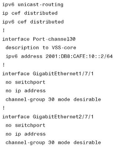
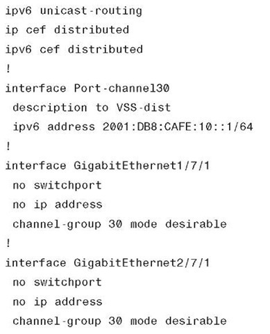
Physical point-to-point links are configured in much the same way as the standalone Catalyst 6500 case, except that now the two switches at the distribution and the core layers act like a single logical switch. Therefore, only one IPv6 address is used on the port channel interfaces (instead of one for each port channel to each switch in a non-VSS model). Example 6-26 is the point-to-point interface configuration for the VSS distribution layer.
Example 6-26 VSS Distribution Layer Configuration (Port-Channel)
Example 6-27 is the point-to-point interface configuration for the VSS core layer.
Example 6-27 VSS Core Layer Configuration (Port-Channel)
As with the standalone switch, the access layer uses a single VLAN per switch. The VLANs do not span access layer switches and are terminated at the distribution layer.
All other configurations, such as routing and VLANs (including access layer switches), remain the same as with the non-VSS deployment.
