First-Hop Redundancy Configuration
The HA design in the DSM consists of running two of each switches (applicable in the distribution, core, and data center aggregation layers) and ensuring that the IPv4 and IPv6 routing configurations are tuned and completely fault-tolerant. All distribution pairs in the reference campus configuration are running HSRP for both IPv4 and IPv6. Optionally, GLBP can be used.
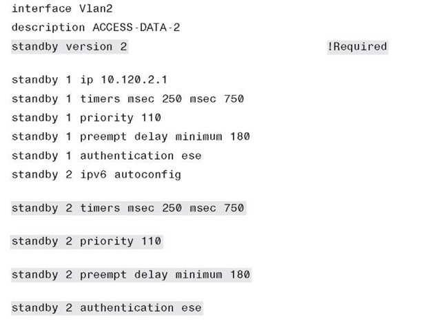
HSRP is defined on a per-interface basis and is mostly configured like HSRP for IPv4. The configuration in Example 6-13 shows both HSRP for IPv4 and IPv6 for comparison. The IPv6 for HSRP configuration shown has HSRP version 2 enabled and is used to take advantage of several new features such as the advertisement and learning of millisecond timer values, expanded group range, and IPv6 support.
When configuring a standby virtual IPv6 address, there are two options: a manually defined link-local address (FE80::/10 prefix) or autoconfig. Note that depending on the platform and version of code, a global IPv6 address can be defined as the standby address. The ipv6 autoconfig command is used to generate a link-local address (from the FE80::/10 prefix) that is created from the HSRP virtual MAC address. The HSRP IPv6 virtual MAC address range is 0005.73A0.000-0005.73A0.0FFF.
Both HSRP IPv4 and IPv6 are using lowered hello timers for faster failover as well as adjusted priority values to establish an active/standby role between the 6k-dist-1 and 6k-dist-2 switches. Preemption is configured so that the switch will take back the role of ACTIVE from the lower-priority 6k-dist-2. Preempt delay is configured for 180 seconds because this is a Catalyst 6500 with many line cards. It is a best practice to configure a delay so that the switch does not go ACTIVE for HSRP before all the line cards have been powered on and activated. A delay of 180 seconds gives enough time from power-up for the line cards to be powered on and activated.
Finally, HSRP authentication has been configured between both distribution layer switches for added security. More information about HSRP for IPv6 can be found at http://www.cisco.com/en/US/docs/ios/ipv6/configuration/guide/ip6-fhrp.html#wp1055254.
The configuration for HSRP for IPv4 and IPv6 on the 6k-dist-1 switch is shown in Example 6-13.
Example 6-13 6k-dist-1 HSRP Configuration
QoS Configuration
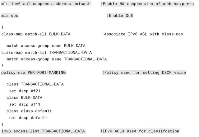
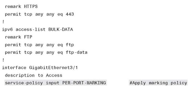
The QoS configurations for the DSM are based on the recommendations found in the Cisco Campus QoS Solutions Reference Network Design (SRND) located here: http://www.cisco.com/en/US/docs/solutions/Enterprise/WAN_and_MAN/QoS_SRND_4 0/QoSCampus_40.html. As was mentioned in the "General Campus IPv6 Deployment Considerations" QoS section, earlier in this topic, the primary consideration for altering or creating a QoS policy to act on both IPv4 and IPv6 is to ensure that the ip keyword is removed from the match and set statements in the policy configuration. The policy criteria are the same for IPv4 and IPv6 unless it is determined that a special set of QoS policies is needed for IPv6 because of the fact that a completely different set of applications might be used for IPv6. The policies for classification, marking, queuing, and policing vary greatly based on customer requirements. The types of queuing and number of queues supported also vary from platform to platform and line card to line card. The reader should ensure that QoS is thoroughly understood before deploying it for either IPv4 or IPv6 because there are many elements to understand and, in many cases, configurations are platform-dependent.
This topic is not meant to be a primer for QoS but simply a reference to show a snippet of the overall QoS policy used. A summarized configuration for the 6500-E series switch is shown in Example 6-14 and is for reference only. For the sake of brevity, not all interfaces and per-interface configurations are shown.
Example 6-14 QoS Example for Catalyst 6500-E
Example 6-14 QoS Example for Catalyst 6500-E
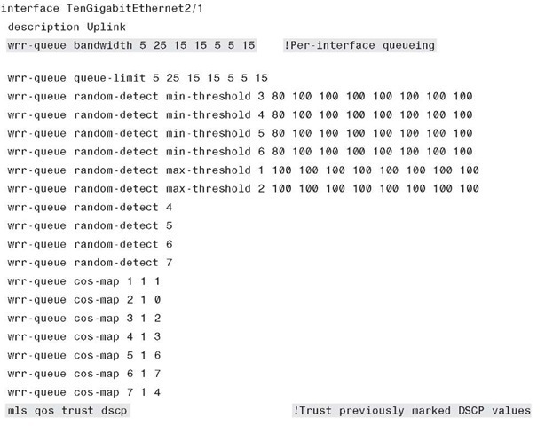
Some features do not require any configuration to get them to see and act on IPv6 traffic. Queuing is an example of when IPv6 traffic is dealt with on a per-interface basis without any special configuration changes. Example 6-15 gives an example of a per-interface queuing configuration that equally applies to IPv4 and IPv6.
Example 6-15 QoS Queuing Example on a 10-Gigabit Ethernet Interface
Multicast Configuration
IPv6 multicast is fully supported in the DSM. One thing to understand is the lack of CLI input required to enable IPv6 multicast when using PIM-SSM or Embedded-RP. If PIM-SSM is used exclusively, it is only required to enable ipv6 multicast-routing globally, which automatically enables PIM on all IPv6-enabled interfaces. This configuration also automatically enables PIM-SSM and its associated group range. This process is a dramatic difference from what is required with IPv4 multicast, where all multicast elements must be configured manually.
In the 3750-acc-1 switch example, the switch needs to have IPv6 multicast awareness to control the distribution of multicast traffic only on ports that are actively listening. This awareness is accomplished by enabling MLD Snooping. IPv6 multicast routing is globally enabled on each Layer 3 device all the way to the source located in the data center.
Although IPv6 multicast design is outside the scope of this topic, configurations are shown for IPv6 multicast on the 3750-acc-1, 6k-dist-1, and 6k-core-1 switches, and the application is leveraging PIM-SSM. After ipv6 multicast-routing has been configured, PIM is enabled, PIM tunnel interface(s) for the source registration process are automatically created, and a PIM-SSM group range is automatically configured by the device. All that needs to be done is to have an MLDv2-capable host access the source application that is configured for the appropriate multicast group.
Most of the configuration examples are trivial, but are shown from the access layer to the aggregation layer for operational consistency:
■ 3750-acc-1: Globally enable MLD Snooping. ipv6 mld snooping
■ 6k-dist-1: Globally enable IPv6 multicast routing. Remember that with IPv6 multicast with PIM, after multicast is globally enabled, IPv6 support for PIM is automatically enabled on any interface that has IPv6 enabled (through static configuration or through IPv6 address assignment).
ipv6 multicast-routing
■ 6k-core-1: Globally enable IPv6 multicast routing.
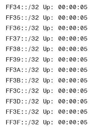
After IPv6 multicast has been enabled globally, you can use the show ipv6 pim range-list command to ensure that the automatic group range for SSM is available, as shown in Example 6-16.
Example 6-16 6k-core-1 – PIM-SSM Range List
The output shown in Example 6-17 on the 3750-acc-1 switch illustrates that the switch can see both distribution layer switches (indicated by the information in the "ports" column) as locally attached multicast routers.
Example 6-17 3750-acc-1 IPv6 Multicast PIM Router Status
When a group is active on the access layer switch, information about the group can be displayed, as shown in Example 6-18.
Example 6-18 3750-acc-1 IPv6 Multicast Group Output
Note There may be scenarios where the host operating system does not support MLDv2 and therefore cannot natively participate in PIM-SSM environments.
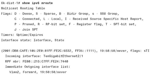
On 6k-dist-1, information about PIM, multicast route, reverse path forwarding (RPF), and groups can be viewed in much the same way as with IPv4. Example 6-19 shows the output of an active group using PIM-SSM (FF35::1111). This stream is coming in from the 6k-core-1 switch and going out the VLAN2 (3750-acc-1) interface.
Example 6-19 6k-dist-1 IPv6 Multicast Route Output
Routed Access Configuration
When using the routed access design, the primary change to the campus implementation applies to the access and distribution layer configurations. With the routed access design, the access layer performs routing, whereas the previous (traditional) design had the access layer as a Layer 2-only component and the first Layer 3 component was in the distribution layer. This topic is not meant to discuss the advantages and disadvantages of the routed access design. However, the failover performance improvements realized, along with the important fact that spanning tree is not an active component, make this design attractive to many customers. Because of customer demand, performance, and operational advantages with the routed access design, this topic discusses implementing IPv6 in this design.
Extending the DSM to now be a routed access design is quite easy. The removal of dependency on a redundant first-hop protocol is also a major improvement in the access layer. Basically, the access layer switches enable IPv6 routing and change the trunk links to routed links, and the distribution layer switches remove the trunks and VLANs for the access layer.
Figure 6-12 shows the updated DSM topology that has the routed access component included. Because nothing has changed upstream of the distribution layer, this diagram includes only the changed layers, which are the access and distribution layers. Also note that the 2001:DB8:CAFE portion of the prefix is removed for clarity in the diagram. Only the subnet identifier (A, B, C, or D) and the interface ID are shown.
Figure 6-12 shows that the links between the access layer and distribution layer are now routed links instead of trunked Layer 2 links. IPv6 addressing and routing are configured on the new links, and the hosts in the VLANs use the IPv6 address of the VLAN interface on the access switch as the default gateway.
Figure 6-12 DSM Topology – Routed Access Design
Note For those of you using OSPF in their network, the following IGP configuration is shown using OSPFv3. This is a sample of what the configurations would look like in the campus for OSPFv3 in the routed access model. This is an effort to help you see the IGP configurations for both EIGRP for IPv6 and OSPFv3 in a campus network.
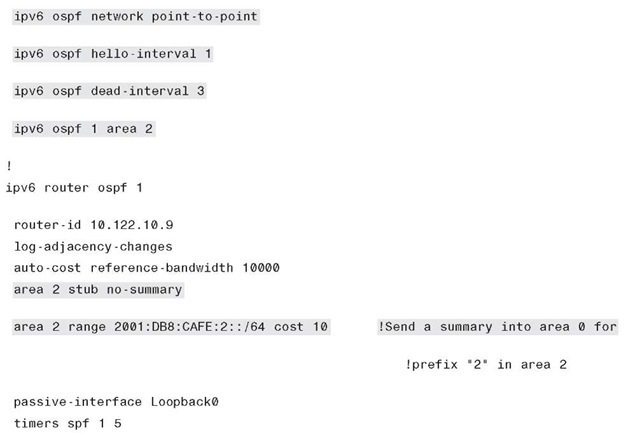
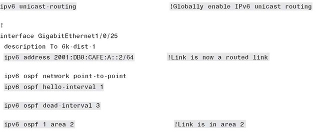
The configuration in Example 6-20 shows the relevant routed access configurations for the 3750-acc-1 switch.
Example 6-20 Routed Access Layer – 3750-acc-1
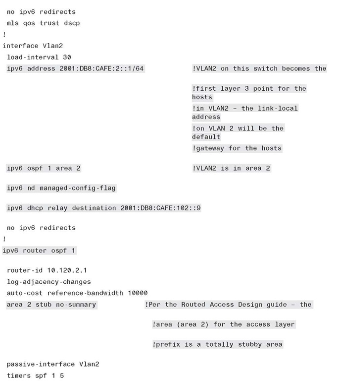
Example 6-21 shows the configuration for the 6k-dist-1 switch. Example 6-21 Routed Access Layer – 6k-dist-1
Example 6-21 Routed Access Layer – 6k-dist-1
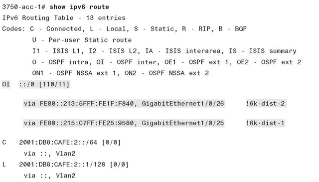
The summary output of the show ipv6 route command for the 3750-acc-1 in Example 622 shows a default route coming from the two distribution layer switches. (The default is injected by the upstream switches where the Internet edge connects to the core layer.)
Example 6-22 3750-acc-1 IPv6 Unicast Route Output
The other configuration change that is made in the DSM when using the routed access design is with IPv6 multicast. Now that the access layer switch is actually routing, the switch needs to be configured to support PIM of whatever variety is used in the rest of the network. The previous multicast configurations shown for the 6k-dist-1 would be deployed at the access layer switches. Note that the customer needs to validate which access layer platforms have IPv6 multicast routing support and in which code version.
Additional information on the Cisco routed access design can be found in the "Additional References" section, later in this topic.




![tmp19-99_thumb[2] tmp19-99_thumb[2]](http://what-when-how.com/wp-content/uploads/2011/09/tmp1999_thumb2_thumb.jpg)
