The following sections focus on the configuration of the DSM. The configurations are divided into specific areas, such as VLAN, routing, and HA configuration. Many of these configurations, such as VLANs and physical interfaces, are not specific to IPv6.
VLAN configurations for the DSM are the same for IPv4 and IPv6, but are shown for completeness.
Note Example configurations are shown for only two switches (generally the pair in the same layer or a pair connecting to each other) and only for the section being discussed, for example, routing or HA.
Network Topology
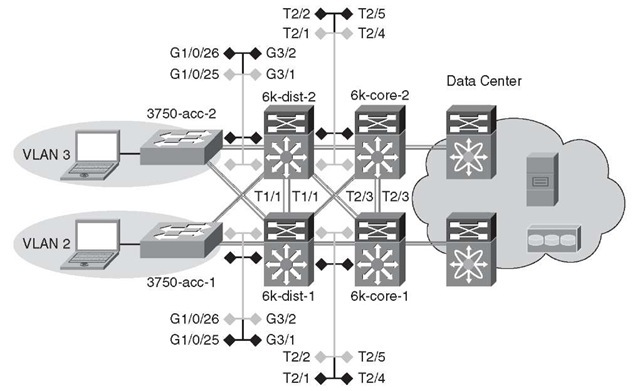
The diagrams in this section are used as a reference for all DSM configuration examples. Figure 6-10 shows the physical port layout that is used for the DSM.
Figure 6-10 DSM Network Topology – Physical Ports
Note Only the details of the campus are shown.
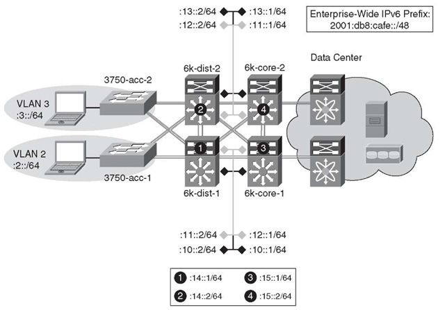
Figure 6-11 shows the IPv6 addressing plan for the DSM environment. To keep the diagram as simple to read as possible, the /48 prefix portion of the network is deleted. The IPv6 /48 prefix used in all the models in this topic is 2001:db8:cafe::/48.
Note The IPv6 addressing used in this topic is by no means meant to be used as a best practice. The addressing used in this topic has a focus on simplicity for the sake of easier flow and readability. You should carefully plan the IPv6 address assignment before fully implementing it. A lot can be learned from an existing IPv4 addressing plan—taking advantage of lessons learned, and perhaps, starting from scratch as the IPv6 address plan is a "greenfield" opportunity to do addressing fresh and clean.
In addition to the physical interfaces, IPv6 addresses are assigned to loopback and VLAN interfaces. Table 6-4 shows the switch, loopback/VLAN interface, and IPv6 address for the interface.
Figure 6-11 DSM Network Topology – IPv6 Addressing
Table 6-4 Switch Loopback/VLAN Addressing
|
Switch |
Interface |
IPv6 Address |
|
3750-acc-1 |
Loopback |
2001:db8:cafe:1f3::5/128 |
|
VLAN2 |
2001:db8:cafe:2::4/64 |
|
|
3750-acc-2 |
Loopback |
2001:db8:cafe:1f3::6/128 |
|
VLAN3 |
2001:db8:cafe:3::4/64 |
|
|
6k-dist-1 |
Loopback |
2001:db8:cafe:1f3::3/128 |
|
VLAN2 |
2001:db8:cafe:2::2/64 |
|
|
VLAN3 |
2001:db8:cafe:3::2/64 |
|
|
6k-dist-2 |
Loopback |
2001:db8:cafe:1f3::4/128 |
|
VLAN2 |
2001:db8:cafe:2::3/64 |
|
|
VLAN3 |
2001:db8:cafe:3::3/64 |
|
|
6k-core-1 |
Loopback |
2001:db8:cafe:1f3::1/128 |
|
6k-core-2 |
Loopback |
2001:db8:cafe:1f3::2/128 |
Physical/VLAN Configuration
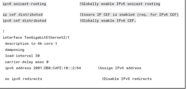
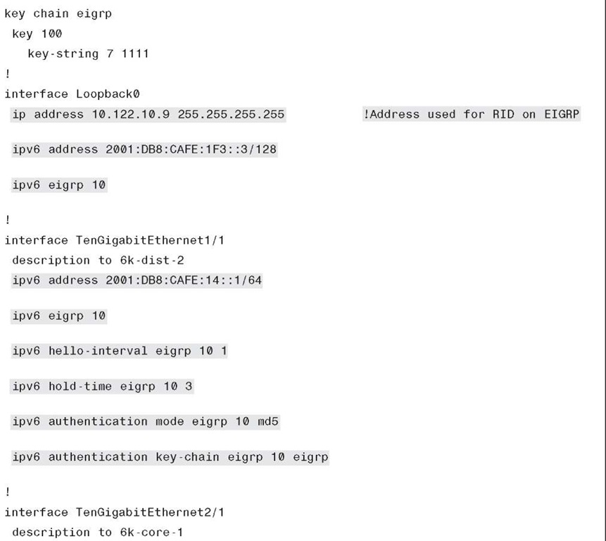
Physical point-to-point (p2p) links are configured in much the same way as IPv4. Example 6-7 is the p2p interface configuration for the link between 6k-dist-1 and 6k-core-1.
Example 6-7 6k-dist-1 P2P Link Configuration
The configurations include the no ipv6 redirects command. This turns off the default capabilities for sending ICMPv6 redirects (signaling a better route to a host), which are not needed on these links. It is a best practice to disable unneeded services on networking and host devices, especially those that might be used as a security attack target.
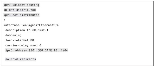
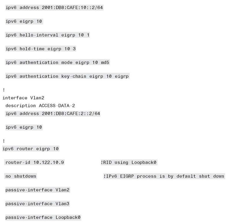
Example 6-8 shows the IPv6-specific configuration for the core-to-distribution link.
Example 6-8 6k-core-1 P2P Link Configuration
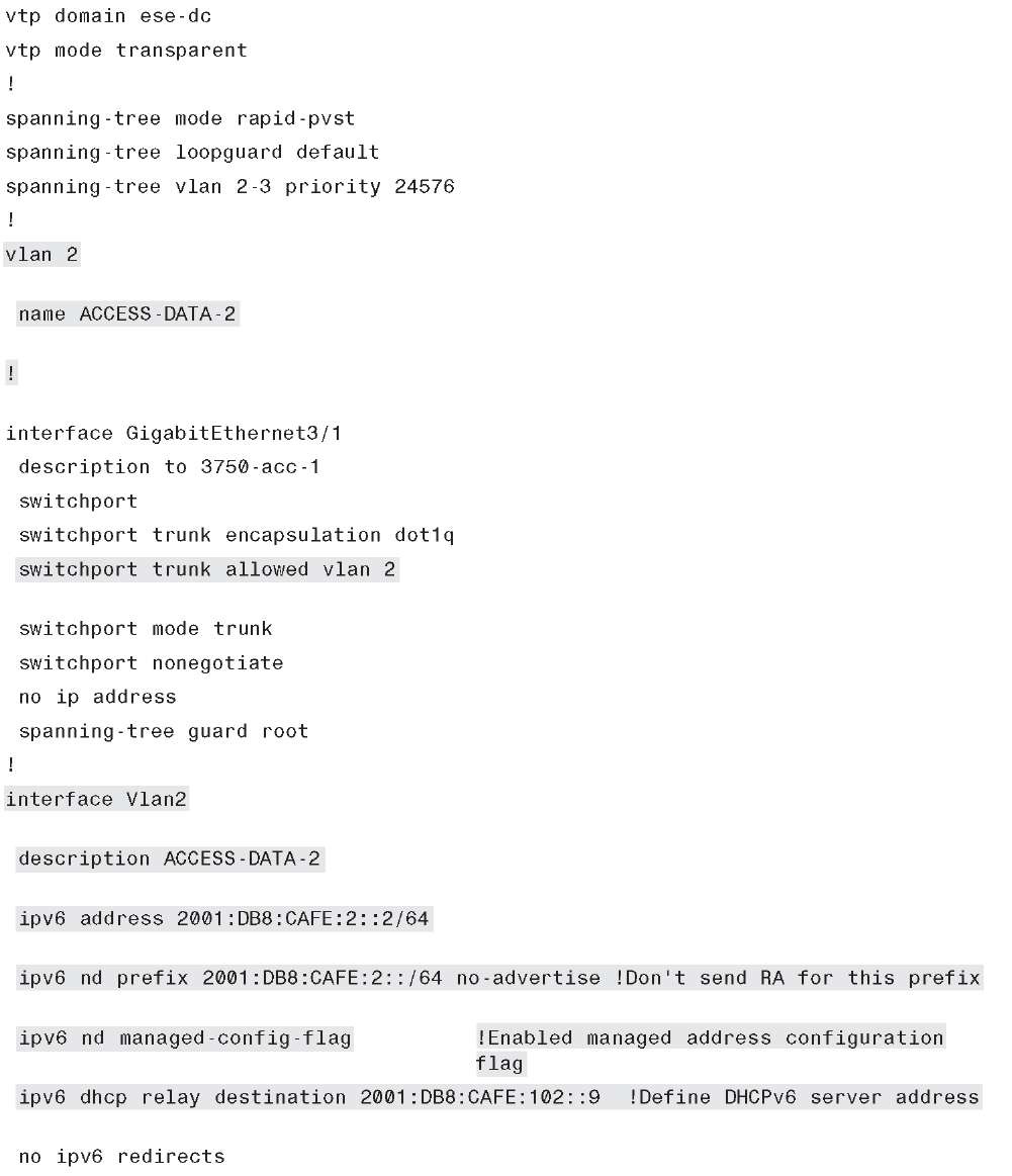
Example 6-9 shows the 6k-dist-1 VLAN2 configuration. The configuration shows a trunk link to the access layer and a data VLAN (VLAN2). In this example, DHCPv6 relay is enabled for the hosts attached to this VLAN. The line with no-advertise is used to prevent the prefix listed from being sent in an RA. This is most often used to prevent non-DHCPv6-capable clients that are on the link from using SLAAC. If you have a mixed environment of DHCPv6-capable and non-IPv6 DHCPv6-capable hosts and want to receive addressing regardless of method, do not use this command. The managed-config-flag command signals the client to use stateful address configuration (DHCPv6).
Example 6-9 6k-dist-1 VLAN2 Configuration
On the Catalyst 3750 and 3560 switches, you must enable the correct Switch Database Management (SDM) template to allow the ternary content addressable memory (TCAM) to be used for different purposes. The 3750-acc-1 and 3750-acc-2 have been configured with the "dual-ipv4-and-ipv6" SDM template using the sdm prefer dual-ipv4-and-ipv6 default command (this requires a reboot). For more information about the sdm prefer command and associated templates, refer to the following URL: http://tinyurl.com/28qj5lk.
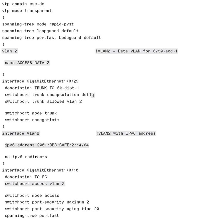
The access layer uses a single VLAN per switch; other VLANs such as management or voice VLANs are not discussed. The VLANs do not span access layer switches and are terminated at the distribution layer. Example 6-10 shows the 3750-acc-1 configuration.
Example 6-10 3750-acc-1 VLAN Configuration
Although stacks are not used in any of the models discussed here, they are commonly used on the Catalyst 3750 and 3560 switches in the access layer. IPv6 is supported in much the same way as IPv4 when using switch stacks. For more information on IPv6 with switch stacks, refer to the following URL:http://tinyurl.com/32324vo.
Routing Configuration
As previously mentioned, the routing for the DSM is set up using EIGRP for both IPv4 and IPv6. The EIGRP configuration follows the recommended Cisco campus designs as much as possible.
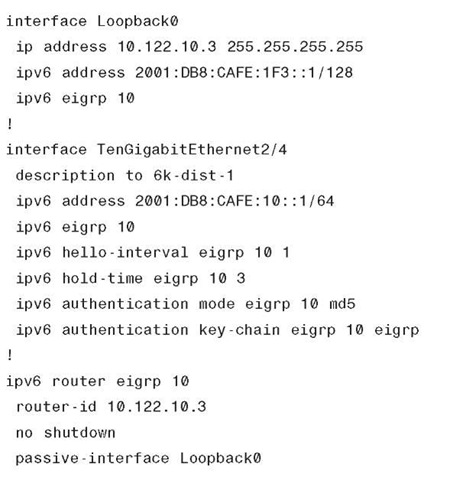
The configuration for EIGRP for IPv6 is shown for the 6k-dist-1 switches in Example 6-11.
Example 6-11 6k-dist-1 Routing Configuration
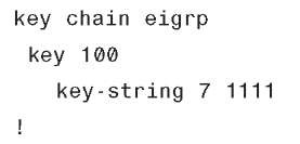
EIGRP is configured on a per-interface basis. Per the Cisco campus design guides, the EIGRP hello and hold timers are modified for faster convergence and EIGRP authentication is enabled. The router ID for the EIGRP process remains 32 bits long and is derived from an IPv4 address found on one of the configured interfaces or manually defined. Additionally, it is recommended to configure an IPv6 EIGRP summary range that would be advertised towards the core. This is done by using the command ipv6 summary-address eigrp. If the router is IPv6-only, the EIGRP router ID must be manually configured.
The configuration for EIGRP for IPv6 is shown for the 6k-core-1 switches in Example 612. Only a portion of the configuration is shown because redundant links between the distribution and core layers share identical configurations as they relate to routing.
Example 6-12 6k-core-1 Routing Configuration
It is important to read and understand the implications of modifying various IGP timers. The campus network should be designed to converge as fast as possible. The campus network is also capable of running much more tightly tuned IGP timers than in a branch or WAN environment. The routing configurations shown are based on the Cisco campus recommendations. You should understand the context of each command and the timer value selection before pursuing the deployment in a live network. Refer to the "Additional References" section, later in this topic, for links to the Cisco campus design best practice documents.
