7.1
The concept of field orientation, proposed by Hasse in 1969 and Blaschke in 1972, constitutes, arguably, the most important paradigm in the theory and practice of control of induction motors. In essence, the objective of field orientation is to make the induction motor emulate the separately excited dc machine as a source of adjustable torque. Therefore, we will first review fundamentals of torque production and control in the dc motor.
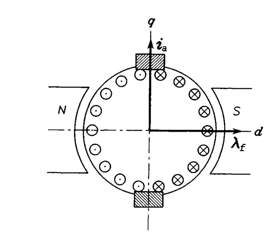
A simplified representation of the dc motor is shown in Figure 7.1.
The pair of magnetic poles, N and S, represent the magnetic circuit of stator, that is, the field part of the machine. Therefore, the space vector, Xf, of flux (flux linkage) generated by the field winding, is stationary and aligned with the d axis of the stator. Thanks to the action of commutator (not shown) and properly positioned brushes, the distribution of armature current in the rotor winding is such that the space vector, ia, of this current is always aligned with the q axis, even though the rotor is revolving.
Practical dc motors are equipped with auxiliary windings designated to neutralize the so-called armature reaction,
that is, weakening of the main magnetic field by the MMF produced by the armature current. Then, the developed torque, TM, is proportional to the vector product of i’a and Xf, that is, to the sine of angle between these vectors. As seen in Figure 7.1, this is always a right angle, which ensures the highest torque-per-ampere ratio. Thus, the torque is produced under optimal conditions, the minimum possible armature current causing minimum losses in the motor and supply system.
In the separately excited dc machine,
the field current, i{, producing Xj and the armature current, i’a, flow in separate windings. Therefore, they can be controlled independently. Usually, particularly under high-load operating conditions, the flux is kept constant at the rated level within the speed range of zero to the rated value. Field weakening, that is, flux reduction in inverse proportion to the speed, is used at speeds higher than rated. With low loads, the motor efficiency can be improved by reducing the flux to such a trade-off value that the resultant decrease in core losses offsets the simultaneous increase in copper losses. In drives that most of

FIGURE 7.1 Simplified representation of the dc motor.
the time run well under the full load, such efficiency optimization schemes can bring significant energy savings.
Presented considerations explain why the separately excited dc motor were for many decades the favorite actuator in motion control systems. The dc motor not only generates the torque under the optimal condition of orthogonality of the flux and current vectors, but it also allows fully independent (“decoupled”) control of the torque and the magnetic field. The torque equation, to be used as a reference for the field-oriented induction motor, can be written as
![tmp323-54_thumb[1] tmp323-54_thumb[1]](http://lh6.ggpht.com/_X6JnoL0U4BY/S1h1L8KeXWI/AAAAAAAAISo/DzoDOs-FLdE/tmp32354_thumb1_thumb.png?imgmax=800)
where kT is a constant dependent on the construction and size of the motor.
